


MDS-E/EH Series Instruction Manual
8 Maintenance
434
IB-1501229-F
< For the spindle motor SJ-VL Series>
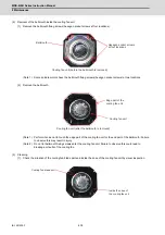
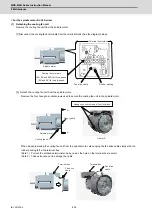
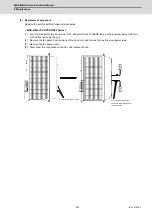
(1) Detaching the cooling fan unit
Remove the cooling fan unit from the spindle motor.
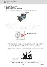
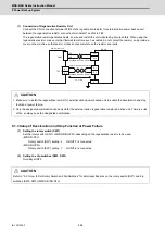
[1] Disconnect the cooling fan's terminals from the terminal block (See the diagram below).
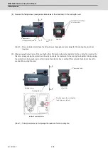
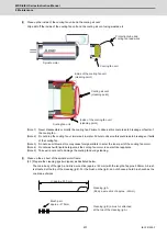
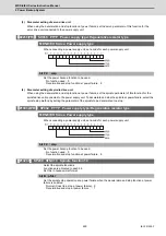
[2] Detach the cooling fan unit from the spindle motor.
Remove the four hexagon socket screws used to secure the cooling fan unit to the spindle motor.
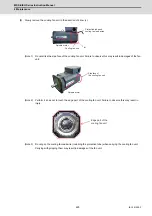
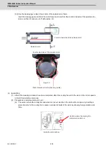
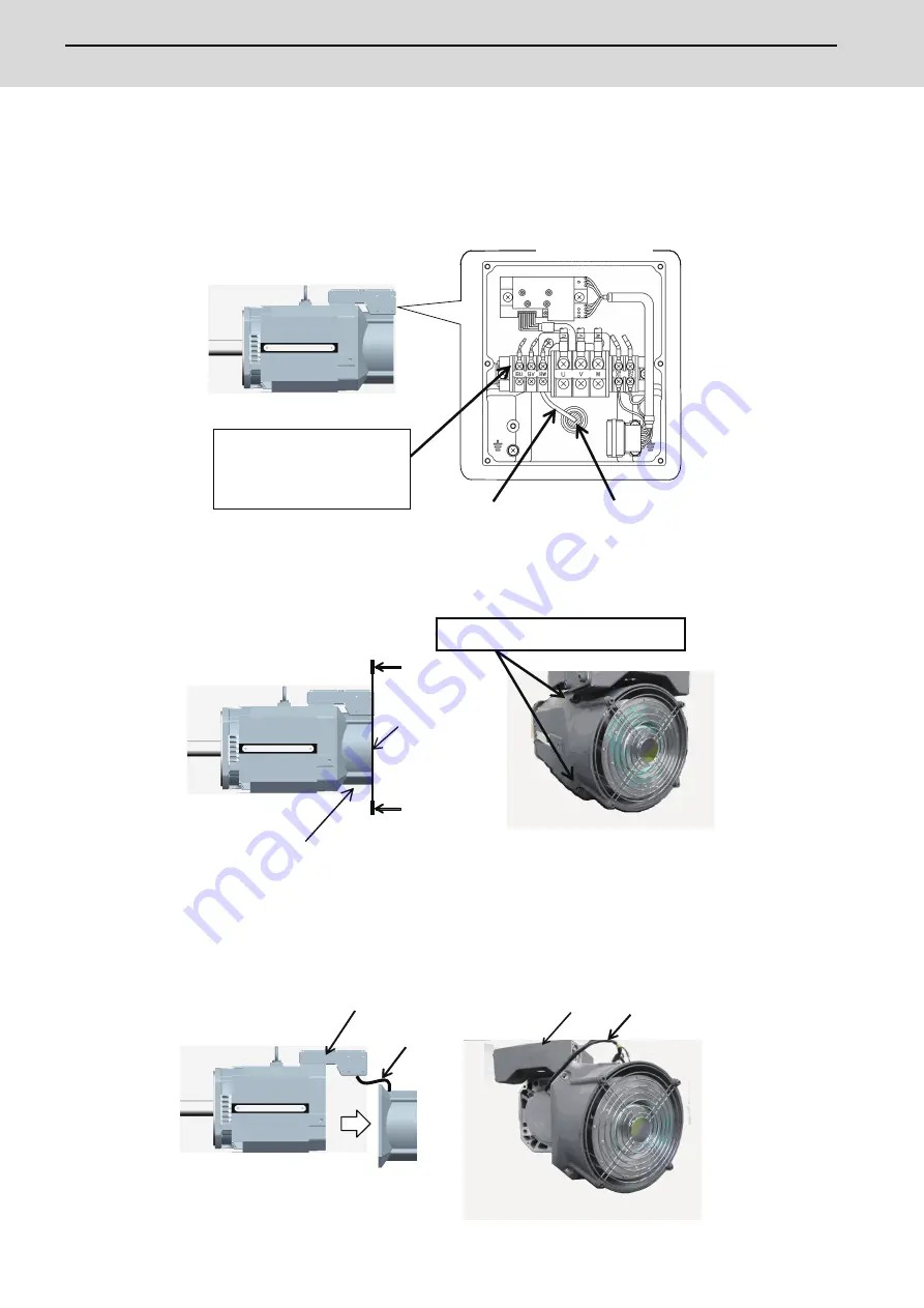
When slowly removing the cooling fan unit from the spindle motor, also unplug the fan drive cable slowly with the
rubber packing left in the terminal box.
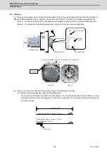
(Note 1) Pull out the solderless terminals one by one as the hole on the terminal box is small.
(Note 2) Take extra care not to damage the cable.
Terminal box inside
Rubber packing
Fan drive cable
Cooling fan terminals
(BU, BV and BW) for three-phase
(BU and BV) for single-phase
Spindle motor
A
A
View A-A
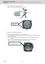
Cooling fan unit
Spindle motor
Finger guard
Hexagon socket screws at four locations.
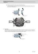
Terminal box
Fan drive
cable
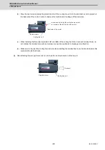
Terminal box
Fan drive
cable
Summary of Contents for MDS-E
Page 1: ......
Page 3: ......
Page 15: ......
Page 17: ......
Page 19: ......
Page 21: ......
Page 31: ......
Page 32: ...1 IB 1501229 F 1 Installation ...
Page 76: ...45 IB 1501229 F 2 Wiring and Connection ...
Page 132: ...101 IB 1501229 F 3 Safety Function ...
Page 142: ...111 IB 1501229 F 4 Setup ...
Page 277: ...MDS E EH Series Instruction Manual 4 Setup 246 IB 1501229 F ...
Page 278: ...247 IB 1501229 F 5 Servo Adjustment ...
Page 351: ...MDS E EH Series Instruction Manual 5 Servo Adjustment 320 IB 1501229 F ...
Page 352: ...321 IB 1501229 F 6 Spindle Adjustment ...
Page 404: ...373 IB 1501229 F 7 Troubleshooting ...
Page 455: ...MDS E EH Series Instruction Manual 7 Troubleshooting 424 IB 1501229 F ...
Page 456: ...425 IB 1501229 F 8 Maintenance ...
Page 475: ...MDS E EH Series Instruction Manual 8 Maintenance 444 IB 1501229 F ...
Page 476: ...445 IB 1501229 F 9 Power Backup System ...
Page 494: ...463 IB 1501229 F 10 Appx 1 Cable and Connector Assembly ...
Page 504: ...473 IB 1501229 F 11 Appx 2 D A Output Specifications for Drive Unit ...
Page 514: ...483 IB 1501229 F 12 Appx 3 Protection Function ...
Page 523: ...MDS E EH Series Instruction Manual 12 Appx 3 Protection Function 492 IB 1501229 F ...
Page 524: ...493 IB 1501229 F 13 Appx 4 Compliance to EC Directives ...
Page 528: ...497 IB 1501229 F 14 Appx 5 EMC Installation Guidelines ...
Page 540: ...509 IB 1501229 F 15 Appx 6 Higher Harmonic Suppression Measure Guidelines ...
Page 550: ......
Page 554: ......


