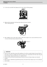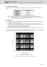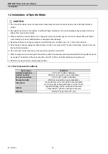
MDS-E/EH Series Instruction Manual
1 Installation
16
IB-1501229-F
1.2.5 Coupling with the Fittings
[1] We recommend you to adjust the dynamic balance (field balance) before fastening a belt.
[2] The position deviation in the axial direction between the motor pulley and spindle side pulley should be as small as
possible and perform parallel correcting carefully.
[3] If the selection or tension of belt is incorrect, an excessive force is applied to the shaft end and bearings, which may
result in shorter life or damages.
[4] When the load by the belt exceeds the tolerable radial load of the motor, reselect the motor or belt/pulley.
[5] Use an appropriate tension gauge to measure a belt tension.
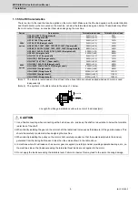
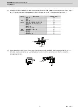
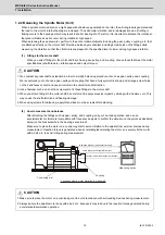
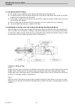
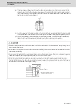
1.2.6 Installation of Rotary Joint and Coolant Joint (Hollow Shaft Specifications)
Attach the fittings such as pulley, gear, coupling, and coolant joint to the motor output shaft when connecting a spindle
motor to a spindle. The incorrect selection of fittings or inadequate installation accuracy can generate abnormal vibration
or noise at the coupling. It can also shorten the motor or bearing life, and can damage them (fretting or flaking). Contact
the manufacturer with any questions regarding the fittings mentioned above.
< Reference > Bearing damage
Fretting:
Fretting occurs when contact surfaces produce abrasive red-rust powders, which wear contact surfaces and make small
dimples on them. If fretting occurs on the raceway surfaces, dimples are made in the rolling element pitch. Adding
vibration load on the contact parts generates a small amplitude oscillation, which forces out lubrication from those parts
until there is no lubrication, resulting in significant wear.
Flaking:
Flaking occurs when small pieces of bearing raceway surfaces peel off due to rotation fatigue. It may occur in an early
stage due to an excessive load, handling fault, inadequate accuracy of shaft or housing, or a load application by incorrect
installation.
Rotary joint
Coolant joint
Spindle motor
Coupling
Summary of Contents for MDS-E
Page 1: ......
Page 3: ......
Page 15: ......
Page 17: ......
Page 19: ......
Page 21: ......
Page 31: ......
Page 32: ...1 IB 1501229 F 1 Installation ...
Page 76: ...45 IB 1501229 F 2 Wiring and Connection ...
Page 132: ...101 IB 1501229 F 3 Safety Function ...
Page 142: ...111 IB 1501229 F 4 Setup ...
Page 277: ...MDS E EH Series Instruction Manual 4 Setup 246 IB 1501229 F ...
Page 278: ...247 IB 1501229 F 5 Servo Adjustment ...
Page 351: ...MDS E EH Series Instruction Manual 5 Servo Adjustment 320 IB 1501229 F ...
Page 352: ...321 IB 1501229 F 6 Spindle Adjustment ...
Page 404: ...373 IB 1501229 F 7 Troubleshooting ...
Page 455: ...MDS E EH Series Instruction Manual 7 Troubleshooting 424 IB 1501229 F ...
Page 456: ...425 IB 1501229 F 8 Maintenance ...
Page 475: ...MDS E EH Series Instruction Manual 8 Maintenance 444 IB 1501229 F ...
Page 476: ...445 IB 1501229 F 9 Power Backup System ...
Page 494: ...463 IB 1501229 F 10 Appx 1 Cable and Connector Assembly ...
Page 504: ...473 IB 1501229 F 11 Appx 2 D A Output Specifications for Drive Unit ...
Page 514: ...483 IB 1501229 F 12 Appx 3 Protection Function ...
Page 523: ...MDS E EH Series Instruction Manual 12 Appx 3 Protection Function 492 IB 1501229 F ...
Page 524: ...493 IB 1501229 F 13 Appx 4 Compliance to EC Directives ...
Page 528: ...497 IB 1501229 F 14 Appx 5 EMC Installation Guidelines ...
Page 540: ...509 IB 1501229 F 15 Appx 6 Higher Harmonic Suppression Measure Guidelines ...
Page 550: ......
Page 554: ......

