


MDS-E/EH Series Instruction Manual
8 Maintenance
439
IB-1501229-F
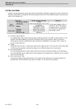
8.3 Adding and Replacing Units and Parts
8.3.1 Replacing the Drive Unit
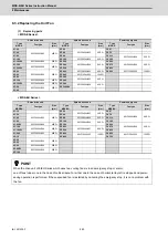
(1) Arrangement of replacing parts
Contact Mitsubishi branch or your dealer for an order or a replacement of the drive unit.
Place an order for the same type of a drive unit as the one to be replaced.
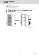
(2) Replacement procedure
Replace the drive unit with the following procedures.
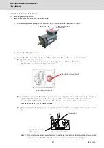
Procedures
[1] Turn the breaker for the input power OFF. Make sure the CHARGE lamp of the power supply unit is turned
OFF.
[2] Disconnect all the connectors and the wires connected to the drive unit.
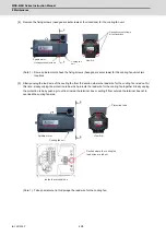
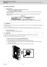
[3] Remove the two (four) screws fixing the drive unit onto the control panel. Remove the drive unit from the
control panel.
[4] Make a same setting for the rotary switch and the dip switch of the new drive unit as those of the uninstalled
drive unit.
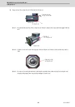
[5] Install a new drive unit by following the removal procedure in reverse.
(3) Restoration
Data backup and restoration is not required before replacing drive units because drive units’ data such as
parameters are stored in the controller. However, carry out a backup of the whole system before replacement as a
precautionary measure.
The power for keeping the encoder’s position data of an absolute position system is supplied from the battery
connected to the drive unit. Keep the power ON once for 30 minutes or more if possible, and make sure to complete
the replacement within 60 minutes after charging the encoder’s capacitor.
CAUTION
1. Correctly transport the product according to its weight. Failure to do so could result in injury.
2. Do not stack the product above the indicated limit.
3. Installation directly on or near combustible materials could result in fires.
4. Install the unit as indicated at a place which can withstand the weight.
5. Do not get on or place heavy objects on the unit. Failure to observe this could result in injury.
6. Always use the unit within the designated environment condition range.
7. Do not allow conductive foreign matter such as screws or metal chips, or combustible foreign matter such as oil enter the
servo drive or servo motor.
8. Do not block the intake or exhaust ports of the servo drive of servo motor. Failure to observe this could result in faults.
9. The servo drive and servo motor are precision devices. Do not drop them or apply strong impacts.
10.Do not install or operate a servo drive or servo motor which is damaged or missing parts.
11.When the unit has been stored for a long time, contact the Service Center or Service Station.
12.Connect the encoder(CN2/CN3) immediately after the installation of the servo drive unit. In addition, when a battery box
is used, immediately connect to the BTA/BTB connector. (prevention of absolute position data lost)
Summary of Contents for MDS-E
Page 1: ......
Page 3: ......
Page 15: ......
Page 17: ......
Page 19: ......
Page 21: ......
Page 31: ......
Page 32: ...1 IB 1501229 F 1 Installation ...
Page 76: ...45 IB 1501229 F 2 Wiring and Connection ...
Page 132: ...101 IB 1501229 F 3 Safety Function ...
Page 142: ...111 IB 1501229 F 4 Setup ...
Page 277: ...MDS E EH Series Instruction Manual 4 Setup 246 IB 1501229 F ...
Page 278: ...247 IB 1501229 F 5 Servo Adjustment ...
Page 351: ...MDS E EH Series Instruction Manual 5 Servo Adjustment 320 IB 1501229 F ...
Page 352: ...321 IB 1501229 F 6 Spindle Adjustment ...
Page 404: ...373 IB 1501229 F 7 Troubleshooting ...
Page 455: ...MDS E EH Series Instruction Manual 7 Troubleshooting 424 IB 1501229 F ...
Page 456: ...425 IB 1501229 F 8 Maintenance ...
Page 475: ...MDS E EH Series Instruction Manual 8 Maintenance 444 IB 1501229 F ...
Page 476: ...445 IB 1501229 F 9 Power Backup System ...
Page 494: ...463 IB 1501229 F 10 Appx 1 Cable and Connector Assembly ...
Page 504: ...473 IB 1501229 F 11 Appx 2 D A Output Specifications for Drive Unit ...
Page 514: ...483 IB 1501229 F 12 Appx 3 Protection Function ...
Page 523: ...MDS E EH Series Instruction Manual 12 Appx 3 Protection Function 492 IB 1501229 F ...
Page 524: ...493 IB 1501229 F 13 Appx 4 Compliance to EC Directives ...
Page 528: ...497 IB 1501229 F 14 Appx 5 EMC Installation Guidelines ...
Page 540: ...509 IB 1501229 F 15 Appx 6 Higher Harmonic Suppression Measure Guidelines ...
Page 550: ......
Page 554: ......


