


MDS-E/EH Series Instruction Manual
8 Maintenance
442
IB-1501229-F
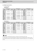
8.3.3 Replacing the Battery
(1) Replacing parts
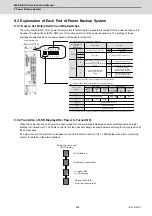
< Replacing a battery equipped with the spindle/servo drive unit
or the battery unit, MDSBTBOX-LR2060 >
When the battery voltage is low (warning 9F), place an order for the same type of a battery as the one currently
equipped with the unit.
Battery type LR20 is commercially available as a size-D alkaline battery. The battery may be purchased and
replaced by the user.
Battery type
(Note)
Four LR20 size-D alkaline batteries are needed for per battery unit, MDSBTBOX-LR2060.
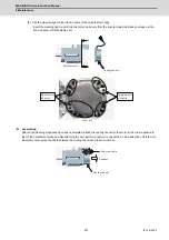
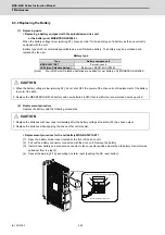
(2) Replacement procedure
Replace the battery with the following procedures.
< Replacement procedure for the cell battery MDS-BAT6V1SET >
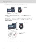
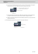
[1] Open the battery holder cover located at the front of the drive unit.
[2] Pull out the battery connector connected with the drive unit. Remove the battery.
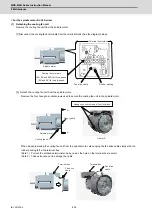
[3] Install a new battery and connect a connector to the connector position where the old battery connector was
pulled out from in step [2].
[4] Cancel the warning 9F by executing an alarm reset (pushing the NC reset button).
Type
Battery equipped unit
MDS-BAT6V1SET
Servo drive unit
LR20 (size-D alkaline battery)
Battery unit, MDSBTBOX-LR2060
CAUTION
1. When the battery voltage is low (warning 9F), do not shut OFF the power of the drive unit until replacement of the battery
to protect the data.
2. Replace the MDSBTBOX-LR2060 battery with new batteries (LR20) that is within the recommended service period.
CAUTION
1. Replace the batteries with new ones immediately after the battery voltage drop alarm (9F) has been output.
2. Replace the batteries while applying the drive unit’s control power.
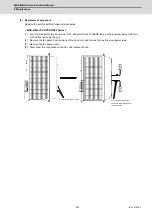
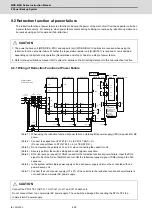
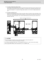
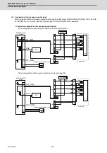
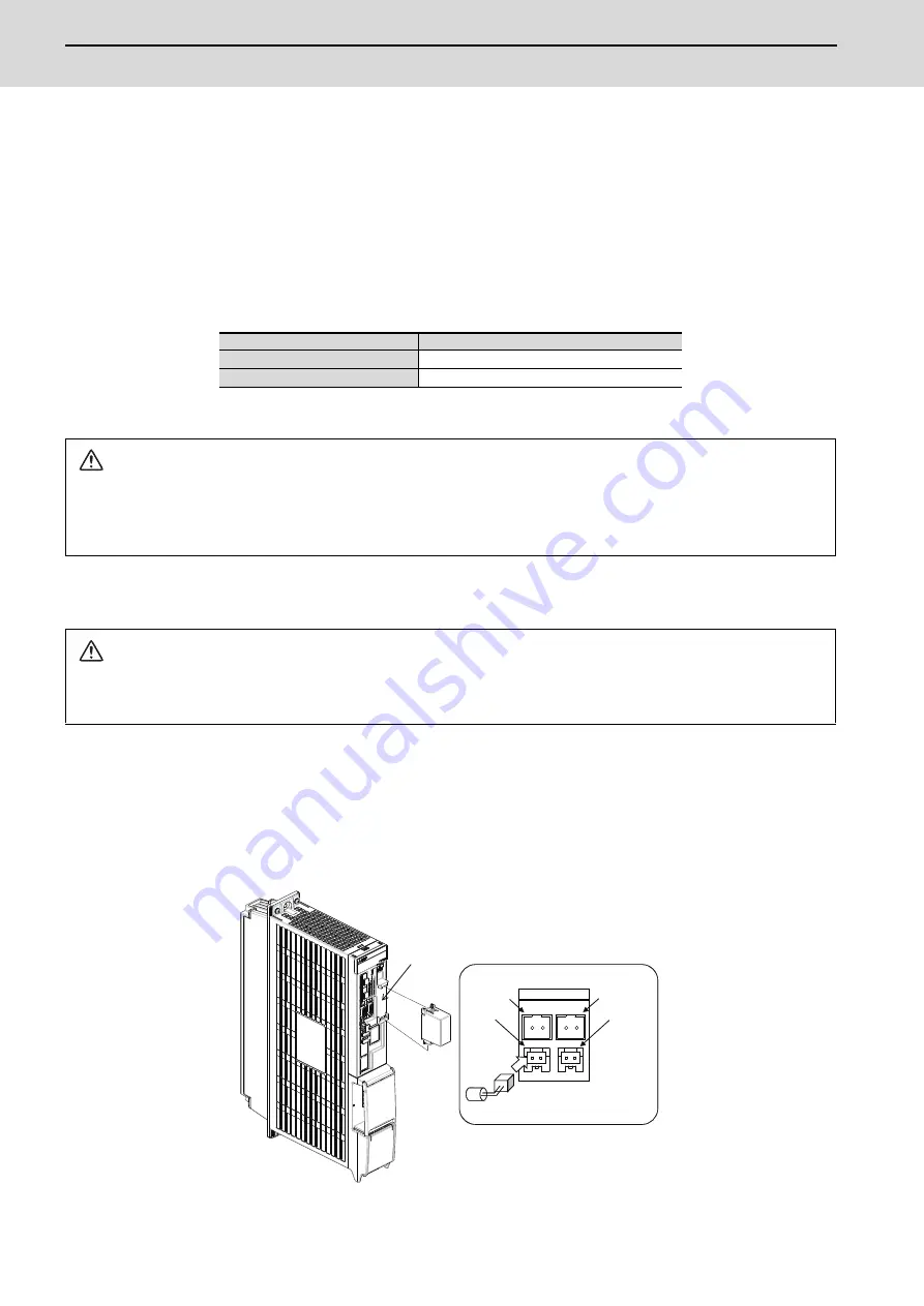
1 2 1 2
1
1
2
2
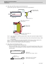
BTI
BTO
BTA
BTB
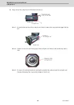
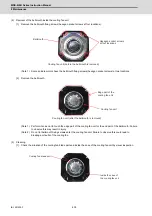
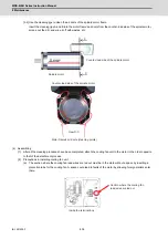
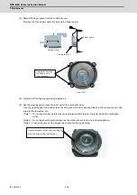
Connect the battery box with BTI.
Battery connector connection part magnified figure
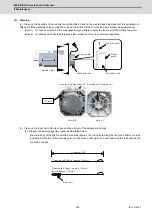
Battery attaching part
Battery unit
Summary of Contents for MDS-E
Page 1: ......
Page 3: ......
Page 15: ......
Page 17: ......
Page 19: ......
Page 21: ......
Page 31: ......
Page 32: ...1 IB 1501229 F 1 Installation ...
Page 76: ...45 IB 1501229 F 2 Wiring and Connection ...
Page 132: ...101 IB 1501229 F 3 Safety Function ...
Page 142: ...111 IB 1501229 F 4 Setup ...
Page 277: ...MDS E EH Series Instruction Manual 4 Setup 246 IB 1501229 F ...
Page 278: ...247 IB 1501229 F 5 Servo Adjustment ...
Page 351: ...MDS E EH Series Instruction Manual 5 Servo Adjustment 320 IB 1501229 F ...
Page 352: ...321 IB 1501229 F 6 Spindle Adjustment ...
Page 404: ...373 IB 1501229 F 7 Troubleshooting ...
Page 455: ...MDS E EH Series Instruction Manual 7 Troubleshooting 424 IB 1501229 F ...
Page 456: ...425 IB 1501229 F 8 Maintenance ...
Page 475: ...MDS E EH Series Instruction Manual 8 Maintenance 444 IB 1501229 F ...
Page 476: ...445 IB 1501229 F 9 Power Backup System ...
Page 494: ...463 IB 1501229 F 10 Appx 1 Cable and Connector Assembly ...
Page 504: ...473 IB 1501229 F 11 Appx 2 D A Output Specifications for Drive Unit ...
Page 514: ...483 IB 1501229 F 12 Appx 3 Protection Function ...
Page 523: ...MDS E EH Series Instruction Manual 12 Appx 3 Protection Function 492 IB 1501229 F ...
Page 524: ...493 IB 1501229 F 13 Appx 4 Compliance to EC Directives ...
Page 528: ...497 IB 1501229 F 14 Appx 5 EMC Installation Guidelines ...
Page 540: ...509 IB 1501229 F 15 Appx 6 Higher Harmonic Suppression Measure Guidelines ...
Page 550: ......
Page 554: ......


