MDS-E/EH Series Instruction Manual
1 Installation
17
IB-1501229-F
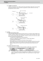
(1) Rotary joint
(a) Installation
Rotary joints are used to supply/exhaust high pressure fluid or liquid which is equal to or lower than the
atmospheric pressure from the fixed pipe to rotary parts of each mechanical device with no leakage. When
attaching a separate external-support type rotary joint to the shaft rear end, structure the rotary joint so that
cutting fluid (drain), which is generated when switching ON/OFF the coolant pressure, does not enter inside of
the motor.
(i)
Provide notches or drain so that the cutting fluid (drain) that has entered the rotary joint housing will not
accumulate.
(ii) A rotary joint is a consumable part. Check and replace regularly.
(iii) Many notches must be provided on the housing as a large amount of cutting fluid may leak if the rotary
joint is damaged.
(iv) If the motor is used vertically facing down, enhance the drain using parts such as an air purge.
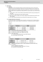
(b) Recommended models of rotary joint
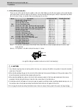
The tables below show the recommended models manufactured by Deublin and Rix. The target models are
designed to have these rotary joints attached to the shaft rear end. Contact the manufacturer for details of
rotary joint.
< Deublin >
(Note 1) Housing both for straight and angle is also available.
(Note 2) Air service with dry running is not available during rotation.
(Note 3) Air service with dry running is also available during rotation.
Contact: Deublin Japan Limited
2-13-1 Minamihanayashiki Kawanishi City, Hyogo, 666-0026 Japan
TEL: 072-757-0099 / FAX: 072-757-0120
< Rix >
(Note)
Available only during rotation and with no pressure (Available during rotation without liquid)
Contact: Rix Corporation
Production Headquarter Product Division
1321-7 Ueki, Kasuyagun Suemachi, Fukuoka 811-2112 Japan
TEL: 092-935-8773 / FAX: 029-936-2815
Screw size
Inner diameter
of shaft end
Coolnat
Oil mist
M16×1.5
(Left-handed screw)
Φ
18
1121-400-345
(Note 1) (Note 2)
1124-036-301
(Note 1) (Note 3)
M12×1.25
(Left-handed screw)
Φ
14
1121-400-327
(Note 1) (Note 2)
1124-400-327
(Note 1) (Note 3)
Screw size
Inner diameter
of shaft end
Coolnat
Oil mist
M16×1.5
(Left-handed screw)
Φ
18
ESX20M-E016 (Note)
ESX20V-E016
M12×1.25
(Left-handed screw)
Φ
14
ESX20M-E012 (Note)
ESX20V-E012
Summary of Contents for MDS-E
Page 1: ......
Page 3: ......
Page 15: ......
Page 17: ......
Page 19: ......
Page 21: ......
Page 31: ......
Page 32: ...1 IB 1501229 F 1 Installation ...
Page 76: ...45 IB 1501229 F 2 Wiring and Connection ...
Page 132: ...101 IB 1501229 F 3 Safety Function ...
Page 142: ...111 IB 1501229 F 4 Setup ...
Page 277: ...MDS E EH Series Instruction Manual 4 Setup 246 IB 1501229 F ...
Page 278: ...247 IB 1501229 F 5 Servo Adjustment ...
Page 351: ...MDS E EH Series Instruction Manual 5 Servo Adjustment 320 IB 1501229 F ...
Page 352: ...321 IB 1501229 F 6 Spindle Adjustment ...
Page 404: ...373 IB 1501229 F 7 Troubleshooting ...
Page 455: ...MDS E EH Series Instruction Manual 7 Troubleshooting 424 IB 1501229 F ...
Page 456: ...425 IB 1501229 F 8 Maintenance ...
Page 475: ...MDS E EH Series Instruction Manual 8 Maintenance 444 IB 1501229 F ...
Page 476: ...445 IB 1501229 F 9 Power Backup System ...
Page 494: ...463 IB 1501229 F 10 Appx 1 Cable and Connector Assembly ...
Page 504: ...473 IB 1501229 F 11 Appx 2 D A Output Specifications for Drive Unit ...
Page 514: ...483 IB 1501229 F 12 Appx 3 Protection Function ...
Page 523: ...MDS E EH Series Instruction Manual 12 Appx 3 Protection Function 492 IB 1501229 F ...
Page 524: ...493 IB 1501229 F 13 Appx 4 Compliance to EC Directives ...
Page 528: ...497 IB 1501229 F 14 Appx 5 EMC Installation Guidelines ...
Page 540: ...509 IB 1501229 F 15 Appx 6 Higher Harmonic Suppression Measure Guidelines ...
Page 550: ......
Page 554: ......

