


MDS-E/EH Series Instruction Manual
9 Power Backup System
451
IB-1501229-F
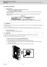
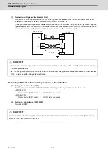
(1) Connection of Regenerative Resistor Unit
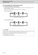
If the spindle motor is decelerated to a stop after servo retraction has been performed using the retraction function
at power failure, the regenerative resistor unit (R-UNIT6,7) is required. When connecting the regenerative resistor
unit, wire it according to "9.1.3 Connection of Regenerative Resistor Unit (1) Connection of Regenerative Resistor
Unit".
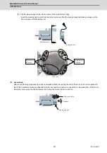
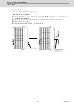
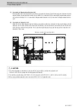
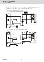
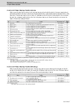
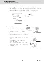
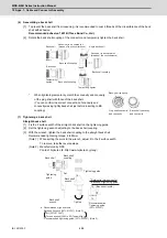
(2) Connection of Capacitor Unit
Study the control panel design using the following connection methods as reference for the power backup unit and
capacitor unit. Connect with the wire whose size is HIV22sq or more and wire the connection wires so that the two
wires closely contact with fixing bands. The connection length between the power backup unit and capacitor unit
should be 10m or less.
CAUTION
1. Only the designated combination can be used for the power backup unit and the capacitor unit.
There is a risk of fire, so always use the designated combination.
2. Connect the power backup unit's TE4(C+,C-) to the capacitor unit's TE1(C+,C-), and do not reverse the polarity.
3. When using multiple capacitor units, connect with TE2 (C+,C-) of capacitor units.
10m or less
Fixing band
Maximum number of connecting units: 6
Summary of Contents for MDS-E
Page 1: ......
Page 3: ......
Page 15: ......
Page 17: ......
Page 19: ......
Page 21: ......
Page 31: ......
Page 32: ...1 IB 1501229 F 1 Installation ...
Page 76: ...45 IB 1501229 F 2 Wiring and Connection ...
Page 132: ...101 IB 1501229 F 3 Safety Function ...
Page 142: ...111 IB 1501229 F 4 Setup ...
Page 277: ...MDS E EH Series Instruction Manual 4 Setup 246 IB 1501229 F ...
Page 278: ...247 IB 1501229 F 5 Servo Adjustment ...
Page 351: ...MDS E EH Series Instruction Manual 5 Servo Adjustment 320 IB 1501229 F ...
Page 352: ...321 IB 1501229 F 6 Spindle Adjustment ...
Page 404: ...373 IB 1501229 F 7 Troubleshooting ...
Page 455: ...MDS E EH Series Instruction Manual 7 Troubleshooting 424 IB 1501229 F ...
Page 456: ...425 IB 1501229 F 8 Maintenance ...
Page 475: ...MDS E EH Series Instruction Manual 8 Maintenance 444 IB 1501229 F ...
Page 476: ...445 IB 1501229 F 9 Power Backup System ...
Page 494: ...463 IB 1501229 F 10 Appx 1 Cable and Connector Assembly ...
Page 504: ...473 IB 1501229 F 11 Appx 2 D A Output Specifications for Drive Unit ...
Page 514: ...483 IB 1501229 F 12 Appx 3 Protection Function ...
Page 523: ...MDS E EH Series Instruction Manual 12 Appx 3 Protection Function 492 IB 1501229 F ...
Page 524: ...493 IB 1501229 F 13 Appx 4 Compliance to EC Directives ...
Page 528: ...497 IB 1501229 F 14 Appx 5 EMC Installation Guidelines ...
Page 540: ...509 IB 1501229 F 15 Appx 6 Higher Harmonic Suppression Measure Guidelines ...
Page 550: ......
Page 554: ......


