


MDS-E/EH Series Instruction Manual
9 Power Backup System
457
IB-1501229-F
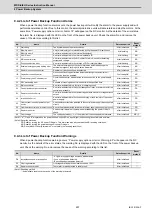
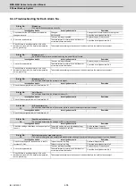
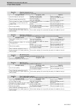
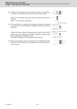
9.4.2 List of Power Backup Function Alarms
When a power backup function alarm occurs, the power backup unit will notify the alarm to the power supply and will
perform deceleration control. Due to this control, the servo/spindle drive units will decelerate and stop the motors. At the
same time, “Power supply option unit error: Alarm 74” will appear on the NC monitor. As the details of the error status,
the alarm No. is displayed with the LED on the front of the power backup unit. Check the alarm No. and remove the
cause of the alarm according to this list.
(Note 1)"b", "C" and "d" displayed on the power backup unit's LED as a solid light (not flickering) do not indicate an alarm.
(Note 2)Resetting methods
PR: Reset by turning the NC power ON again. This alarm can also be reset with the AR resetting conditions.
AR: Reset by turning the power backup unit power ON again.
NR: Reset with NC reset (Alarms with * must satisfy the resetting conditions)
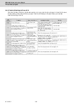
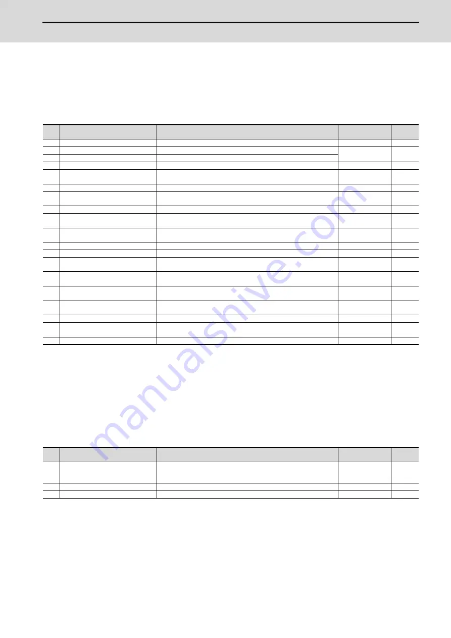
9.4.3 List of Power Backup Function Warnings
When a power backup function warning occurs, “Power supply option unit error: Warning EF” will appear on the NC
monitor. As the details of the error status, the warning No. is displayed with the LED on the front of the power backup
unit. Check the warning No. and remove the cause of the warning according to this list.
(Note1) Resetting method
*: Automatically reset once the cause of the warning is removed.
No.
Name
Details
Detection period
Reset
method
8
Watchdog
The system does not operate correctly.
After initialized
AR
10
Memory error 1
An internal memory error was detected during the power ON self-check.
At initializing
AR
11
Memory error 2
An error was detected in the internal clock signal.
12
Unit ID error
An error was detected in the internal hardware ID.
At initializing
AR
13
A/D converter error
An error was detected in the A/D converter, which is used for detecting
current and voltage.
After initialized
AR
18
Function selection error
An error was detected in the settings of DIP or rotary switches.
At initializing
AR
19
External emergency stop setting error
The external emergency stop cancel state was detected although the
external emergency stop input is set as disabled.
After initialized
AR
1A
Resistor unit connection error
Resistor unit disconnection was detected.
After initialized
AR
1B
Capacitor connection error
Non-connection of capacitor was detected although the capacitor unit
connection is set as enabled.
First ready-ON
AR
1C
Power supply unit Connect error
Communication error was detected in the connection to the power supply
unit.
After initialized
PR
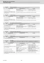
50
S/W processing error
Software processing has not finished within the specified time.
After initialized
PR
51
Main circuit error
An error was detected in a thyristor or charging circuit.
After initialized
PR
52
Control power output circuit error
An error was detected in the output changeover relay or power output of the
control power supply.
After initialized
PR
53
Resistor unit circuit error
An error was detected in the resistor regeneration transistor or regeneration
output.
After initialized
PR
54
Inrush circuit error
An error was detected in the rush circuit relay or rush resistor of the control
power supply.
After initialized
PR
55
Over current in control power output
circuit
An excessive current was detected in the control power supply backup output
circuit.
After initialized
PR
56
Overheat in control power output circuit An overheat was detected in the control power supply backup output circuit.
After initialized
PR
58
Resistor unit error
An abnormal resistor unit value was detected during the power ON self-
check.
After initialized
PR
90
Over voltage
The voltage between L+/L- of the main circuit has exceeded the tolerance.
After initialized
NR (*)
No.
Name
Details
Detection period
Reset
method
D0
Instantaneous power interruption
- AC power supply voltage decrease was detected.
- Loss of phase was detected.
- Bus voltage decrease was detected.
After initialized
*
D1
Over regeneration
Over-regeneration detection level exceeded 100%.
After initialized
*
D5
Resistor unit overheat
Thermal error was detected in resistor unit.
After initialized
*
Summary of Contents for MDS-E
Page 1: ......
Page 3: ......
Page 15: ......
Page 17: ......
Page 19: ......
Page 21: ......
Page 31: ......
Page 32: ...1 IB 1501229 F 1 Installation ...
Page 76: ...45 IB 1501229 F 2 Wiring and Connection ...
Page 132: ...101 IB 1501229 F 3 Safety Function ...
Page 142: ...111 IB 1501229 F 4 Setup ...
Page 277: ...MDS E EH Series Instruction Manual 4 Setup 246 IB 1501229 F ...
Page 278: ...247 IB 1501229 F 5 Servo Adjustment ...
Page 351: ...MDS E EH Series Instruction Manual 5 Servo Adjustment 320 IB 1501229 F ...
Page 352: ...321 IB 1501229 F 6 Spindle Adjustment ...
Page 404: ...373 IB 1501229 F 7 Troubleshooting ...
Page 455: ...MDS E EH Series Instruction Manual 7 Troubleshooting 424 IB 1501229 F ...
Page 456: ...425 IB 1501229 F 8 Maintenance ...
Page 475: ...MDS E EH Series Instruction Manual 8 Maintenance 444 IB 1501229 F ...
Page 476: ...445 IB 1501229 F 9 Power Backup System ...
Page 494: ...463 IB 1501229 F 10 Appx 1 Cable and Connector Assembly ...
Page 504: ...473 IB 1501229 F 11 Appx 2 D A Output Specifications for Drive Unit ...
Page 514: ...483 IB 1501229 F 12 Appx 3 Protection Function ...
Page 523: ...MDS E EH Series Instruction Manual 12 Appx 3 Protection Function 492 IB 1501229 F ...
Page 524: ...493 IB 1501229 F 13 Appx 4 Compliance to EC Directives ...
Page 528: ...497 IB 1501229 F 14 Appx 5 EMC Installation Guidelines ...
Page 540: ...509 IB 1501229 F 15 Appx 6 Higher Harmonic Suppression Measure Guidelines ...
Page 550: ......
Page 554: ......


