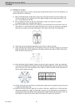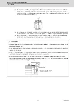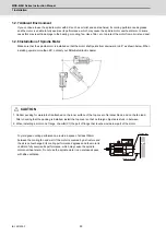
MDS-E/EH Series Instruction Manual
1 Installation
18
IB-1501229-F
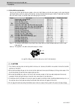
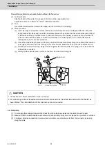
(2) Coolant joint
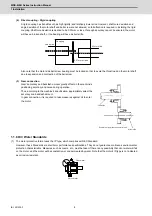
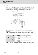
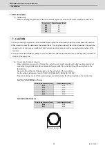
(a) Thrust load of through coolant
When spindle through coolant is used, the thrust load works between the spindle and the motor at the position
A, and between the motor and the rotary joint at the position B in the figure below. Setting the diameter of the
pressured area of the coolant joint attached to the end of the motor shaft appropriately makes the thrust load at
the position B slightly larger than at the position A, which is effective for coolant pump pulsation.
(b) d (the diameter of the pressured area of the coolant joint)
The following are the recommended diameters of the pressured area of the coolant joint installed at the end of
the motor shaft.
(Note)
Effective when the coolant pressure is 6.8MPa or less (Contact the manufacturer if it exceeds
6.8MPa)
(Note)
Without a coolant joint, the thrust load is applied to the motor side by coolant pressure. An excessive
thrust load on the spindle motor may lead to abnormal noise or vibration, or shorten the motor life.
We recommend using an appropriate coolant joint.
Screw size of
shaft head
Company
Rotary joint
Φ
d (diameter of the pressured area
of the coolant joint) (Note)
M16
Deublin
1121-400-345
Φ
12.0
1124-036-301
Φ
10.0
Rix
ESX20M-E016
ESX20V-E016
Φ
11.7
M12
Deublin
1121-400-327
Φ
12.5
1124-400-327
Φ
10.5
Rix
ESX20M-E012
ESX20V-E012
Φ
12.2
A
B
ȭ
d
Motor shaft
Shaft end screw
Coolant joint
Spindle
Motor
Rotary joint
Summary of Contents for MDS-E
Page 1: ......
Page 3: ......
Page 15: ......
Page 17: ......
Page 19: ......
Page 21: ......
Page 31: ......
Page 32: ...1 IB 1501229 F 1 Installation ...
Page 76: ...45 IB 1501229 F 2 Wiring and Connection ...
Page 132: ...101 IB 1501229 F 3 Safety Function ...
Page 142: ...111 IB 1501229 F 4 Setup ...
Page 277: ...MDS E EH Series Instruction Manual 4 Setup 246 IB 1501229 F ...
Page 278: ...247 IB 1501229 F 5 Servo Adjustment ...
Page 351: ...MDS E EH Series Instruction Manual 5 Servo Adjustment 320 IB 1501229 F ...
Page 352: ...321 IB 1501229 F 6 Spindle Adjustment ...
Page 404: ...373 IB 1501229 F 7 Troubleshooting ...
Page 455: ...MDS E EH Series Instruction Manual 7 Troubleshooting 424 IB 1501229 F ...
Page 456: ...425 IB 1501229 F 8 Maintenance ...
Page 475: ...MDS E EH Series Instruction Manual 8 Maintenance 444 IB 1501229 F ...
Page 476: ...445 IB 1501229 F 9 Power Backup System ...
Page 494: ...463 IB 1501229 F 10 Appx 1 Cable and Connector Assembly ...
Page 504: ...473 IB 1501229 F 11 Appx 2 D A Output Specifications for Drive Unit ...
Page 514: ...483 IB 1501229 F 12 Appx 3 Protection Function ...
Page 523: ...MDS E EH Series Instruction Manual 12 Appx 3 Protection Function 492 IB 1501229 F ...
Page 524: ...493 IB 1501229 F 13 Appx 4 Compliance to EC Directives ...
Page 528: ...497 IB 1501229 F 14 Appx 5 EMC Installation Guidelines ...
Page 540: ...509 IB 1501229 F 15 Appx 6 Higher Harmonic Suppression Measure Guidelines ...
Page 550: ......
Page 554: ......

