


MDS-E/EH Series Instruction Manual
9 Power Backup System
460
IB-1501229-F
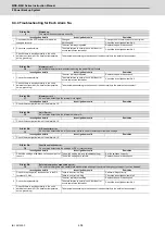
Alarm No.
53
Resistor unit circuit error :
An error was detected in the resistor regeneration transistor or regeneration output.
Investigation details
Investigation results
Remedies
1
Check the reproducibility.
Always reproduced.
Replace the power backup unit.
The state returns to normal once, but the error
occurs sometimes thereafter.
Check the investigation item No. 2.
2
Check if there is any abnormality in the unit's
ambient environment. (Ex. Ambient temperature,
noise, grounding)
Take remedies according to the causes of the abnormality in the ambient environment.
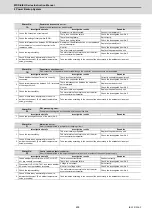
Alarm No.
54
Inrush circuit error :
An error was detected in the rush circuit relay or rush resistor of the control power supply.
Investigation details
Investigation results
Remedies
1
Check the reproducibility.
The error is always repeated.
Replace the power backup unit.
The state returns to normal once, but the error
occurs sometimes thereafter.
Check the investigation item No. 2.
2
Check if there is any abnormality in the unit's
ambient environment. (Ex. Ambient temperature,
noise, grounding)
Take remedies according to the causes of the abnormality in the ambient environment.
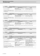
Alarm No.
55
Over-current in control power output circuit :
An excessive current was detected in the control power supply backup output circuit.
Investigation details
Investigation results
Remedies
1
Check whether the control power OUT-L11/OUT-
L21 are correctly connected.
There is connection failure.
Connect correctly.
There is no connection failure.
Check the investigation item No. 2.
2
Check the reproducibility.
The state returns to normal once, but the error
occurs sometimes thereafter.
Check the investigation item No. 3.
3
Check if there is any abnormality in the unit's
ambient environment. (Ex. Ambient temperature,
noise, grounding)
Take remedies according to the causes of the abnormality in the ambient environment.
Alarm No.
56
Overheat in control power output circuit :
An overheat was detected in the control power supply backup output circuit.
Investigation details
Investigation results
Remedies
1
Check the investigation items of the alarm No. 55.
Alarm No.
58
Resistor unit error :
An abnormal resistor unit value was detected during the power ON self-check.
Investigation details
Investigation results
Remedies
1
Check the investigation items of the alarm No. 1A.
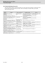
Alarm No.
90
Overvoltage :
The voltage between L+/L- of the main circuit has exceeded the tolerance. The voltage between L+/L- is relatively high
immediately after the occurrence of this alarm. Therefore, wait for 5 minutes or longer until the voltage drops, and then cancel this
alarm by reset.
Investigation details
Investigation results
Remedies
1
Check the reproducibility.
This error occurs every time the motor decelerates
at power failure or at power supply alarm.
Check the investigation item No. 2.
This error occurs occasionally.
Check the investigation item No. 3.
2
Check the machine's load inertia and the maximum
motor rotation speed.
Increased than before.
Decrease the machine’s load inertia and the
maximum motor rotation speed.
No change.
Check the investigation item No. 4.
3
Check the power supply voltage.
Voltage is exceeding the specified maximum
value.
Change the power supply voltage to be within the
specified range.
Voltage is below the specified limit.
Check the investigation item No. 4.
4
Check the capacity of the resistor unit.
Capacity is not sufficient.
Use a resistor unit with a greater capacity.
Capacity is sufficient.
Check the investigation item No. 5.
5
Check if there is any abnormality in the unit's
ambient environment. (Ex. Ambient temperature,
noise, grounding)
Take remedies according to the causes of the abnormality in the ambient environment.
Summary of Contents for MDS-E
Page 1: ......
Page 3: ......
Page 15: ......
Page 17: ......
Page 19: ......
Page 21: ......
Page 31: ......
Page 32: ...1 IB 1501229 F 1 Installation ...
Page 76: ...45 IB 1501229 F 2 Wiring and Connection ...
Page 132: ...101 IB 1501229 F 3 Safety Function ...
Page 142: ...111 IB 1501229 F 4 Setup ...
Page 277: ...MDS E EH Series Instruction Manual 4 Setup 246 IB 1501229 F ...
Page 278: ...247 IB 1501229 F 5 Servo Adjustment ...
Page 351: ...MDS E EH Series Instruction Manual 5 Servo Adjustment 320 IB 1501229 F ...
Page 352: ...321 IB 1501229 F 6 Spindle Adjustment ...
Page 404: ...373 IB 1501229 F 7 Troubleshooting ...
Page 455: ...MDS E EH Series Instruction Manual 7 Troubleshooting 424 IB 1501229 F ...
Page 456: ...425 IB 1501229 F 8 Maintenance ...
Page 475: ...MDS E EH Series Instruction Manual 8 Maintenance 444 IB 1501229 F ...
Page 476: ...445 IB 1501229 F 9 Power Backup System ...
Page 494: ...463 IB 1501229 F 10 Appx 1 Cable and Connector Assembly ...
Page 504: ...473 IB 1501229 F 11 Appx 2 D A Output Specifications for Drive Unit ...
Page 514: ...483 IB 1501229 F 12 Appx 3 Protection Function ...
Page 523: ...MDS E EH Series Instruction Manual 12 Appx 3 Protection Function 492 IB 1501229 F ...
Page 524: ...493 IB 1501229 F 13 Appx 4 Compliance to EC Directives ...
Page 528: ...497 IB 1501229 F 14 Appx 5 EMC Installation Guidelines ...
Page 540: ...509 IB 1501229 F 15 Appx 6 Higher Harmonic Suppression Measure Guidelines ...
Page 550: ......
Page 554: ......


