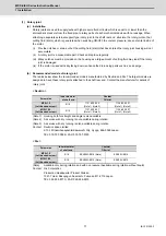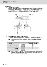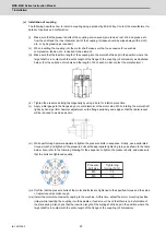
MDS-E/EH Series Instruction Manual
1 Installation
19
IB-1501229-F
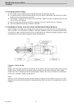
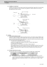
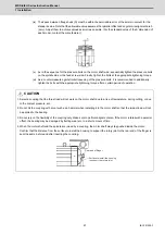
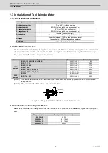
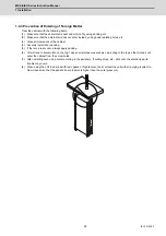
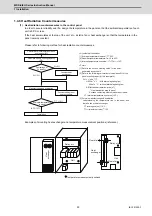
(c) Installation of coolant joint
Install the coolant joint to the motor shaft end so that it stops at the shaft edge. Stopping the coolant joint at the
edge of the inner diameter or at the screw bottom may generate an excessive radial runout, which may
generate abnormal noise or vibration.
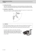
(3) Coupling
(a) Caution when selecting coupling
Always use a flexible coupling for coupling the spindle and the motor. The flexible coupling is flexible enough
to absorb a certain level of radial runout and parallel offset. The flexible coupling has tolerable values for three
degrees of freedom (parallel offset, angular misalignment, and axial movement), which realizes a low-vibration
and low-noise coupling up to high-speed rotation.
- Tolerable values of parallel offset and angular misalignment:
Absorbs minor misalignments or declinations that were not resolved during alignment.
- Tolerable value of axial movement:
Absorbs elongation of the spindle and motor shaft due to thermal expansion.
(These tolerable values are the standard values for which the coupling does not break. They are not the
standard values for which the load is not applied to the spindle or the motor bearing. Thus, in order to
rotate up to high-speed with low-vibration and low-noise, the spindle and the motor shaft must be
aligned.)
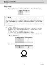
(b) Recommended model of coupling
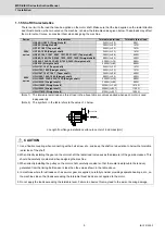
The table below shows the recommended models manufactured by Miki Pulley and Eagle Industry.
(Note)
The diaphragm coupling in the table above absorbs the misalignment of the rotary axis with the
elastic deformation of the extremely thin metal diaphragm. In addition, there are the features as light
weight, no lubrication and high torsional stiffness, so it is recommended as a coupling of a high-
speed motor.
Company
Product name (or Series)
Contact
Miki Pulley
SERVO FLEX
https://www.mikipulley.co.jp/EN/
Eagle Industry
Diaphragm
https://www.ekkeagle.com/en/
Stop at the shaft edge
Stop at the edge of the
inner diameter
Stop at the screw bottom
Motor shaft
Coolant joint
Gap
Gap
Summary of Contents for MDS-E
Page 1: ......
Page 3: ......
Page 15: ......
Page 17: ......
Page 19: ......
Page 21: ......
Page 31: ......
Page 32: ...1 IB 1501229 F 1 Installation ...
Page 76: ...45 IB 1501229 F 2 Wiring and Connection ...
Page 132: ...101 IB 1501229 F 3 Safety Function ...
Page 142: ...111 IB 1501229 F 4 Setup ...
Page 277: ...MDS E EH Series Instruction Manual 4 Setup 246 IB 1501229 F ...
Page 278: ...247 IB 1501229 F 5 Servo Adjustment ...
Page 351: ...MDS E EH Series Instruction Manual 5 Servo Adjustment 320 IB 1501229 F ...
Page 352: ...321 IB 1501229 F 6 Spindle Adjustment ...
Page 404: ...373 IB 1501229 F 7 Troubleshooting ...
Page 455: ...MDS E EH Series Instruction Manual 7 Troubleshooting 424 IB 1501229 F ...
Page 456: ...425 IB 1501229 F 8 Maintenance ...
Page 475: ...MDS E EH Series Instruction Manual 8 Maintenance 444 IB 1501229 F ...
Page 476: ...445 IB 1501229 F 9 Power Backup System ...
Page 494: ...463 IB 1501229 F 10 Appx 1 Cable and Connector Assembly ...
Page 504: ...473 IB 1501229 F 11 Appx 2 D A Output Specifications for Drive Unit ...
Page 514: ...483 IB 1501229 F 12 Appx 3 Protection Function ...
Page 523: ...MDS E EH Series Instruction Manual 12 Appx 3 Protection Function 492 IB 1501229 F ...
Page 524: ...493 IB 1501229 F 13 Appx 4 Compliance to EC Directives ...
Page 528: ...497 IB 1501229 F 14 Appx 5 EMC Installation Guidelines ...
Page 540: ...509 IB 1501229 F 15 Appx 6 Higher Harmonic Suppression Measure Guidelines ...
Page 550: ......
Page 554: ......

