MDS-E/EH Series Instruction Manual
10 Appx. 1: Cable and Connector Assembly
471
IB-1501229-F
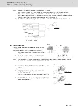
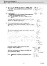
(5) Verifying the direction, insert the crimped contact into the receptacle housing.
After the insertion, pull each wire lightly to make sure that the contacts are fully
inserted. (Lock feeling and sound can be confirmed when the contact is fully/
correctly inserted.)
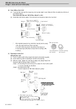
(6) Crimp the ground clip.
As receptacle housing is settled inside a ground clip, it opts for direction according
to the purpose, and positions as shown in the right figure.
(Note)
Direction of receptacle housing is unchangeable after ground slip
crimping.
Positioning the cable jacket end as shown in the right figure. Refer to the Application
Specification (114-5338) and crimp the ground clip.
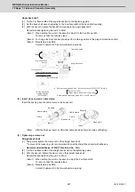
(7) Store the receptacle housing and ground clip in the receptacle case.
Pull the cable side and draw the receptacle housing side as shown in the right figure,
without pushing in it.
Work will become easy when the crimping part of the ground clip is pushed and the
cable is bent as shown in the right figure.
When the ground clip interferes with receptacle case at the position in the right figure
and cause difficulty in continuing to draw in, push the ground clip to distort and drawing
become easy.
(Note)
To prevent a fracture, do not use the ground clip which is bend and unbend 3
times or more.
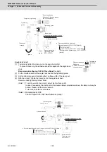
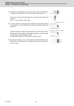
Turn the form of the ground clip back to normal and position it for the
receptacle case as shown in the right figure.
Adjust the projection of receptacle housing to the slit of the receptacle case
and push in until it is fixed to the case.
(Note)
See that the contact of receptacle housing goes inside a ground
clip.
or
1mm
Pull
Push
Push
Distortion
Push
Projection
Contact
Slit
A ground clip is stuck
in a receptacle case.
Summary of Contents for MDS-E
Page 1: ......
Page 3: ......
Page 15: ......
Page 17: ......
Page 19: ......
Page 21: ......
Page 31: ......
Page 32: ...1 IB 1501229 F 1 Installation ...
Page 76: ...45 IB 1501229 F 2 Wiring and Connection ...
Page 132: ...101 IB 1501229 F 3 Safety Function ...
Page 142: ...111 IB 1501229 F 4 Setup ...
Page 277: ...MDS E EH Series Instruction Manual 4 Setup 246 IB 1501229 F ...
Page 278: ...247 IB 1501229 F 5 Servo Adjustment ...
Page 351: ...MDS E EH Series Instruction Manual 5 Servo Adjustment 320 IB 1501229 F ...
Page 352: ...321 IB 1501229 F 6 Spindle Adjustment ...
Page 404: ...373 IB 1501229 F 7 Troubleshooting ...
Page 455: ...MDS E EH Series Instruction Manual 7 Troubleshooting 424 IB 1501229 F ...
Page 456: ...425 IB 1501229 F 8 Maintenance ...
Page 475: ...MDS E EH Series Instruction Manual 8 Maintenance 444 IB 1501229 F ...
Page 476: ...445 IB 1501229 F 9 Power Backup System ...
Page 494: ...463 IB 1501229 F 10 Appx 1 Cable and Connector Assembly ...
Page 504: ...473 IB 1501229 F 11 Appx 2 D A Output Specifications for Drive Unit ...
Page 514: ...483 IB 1501229 F 12 Appx 3 Protection Function ...
Page 523: ...MDS E EH Series Instruction Manual 12 Appx 3 Protection Function 492 IB 1501229 F ...
Page 524: ...493 IB 1501229 F 13 Appx 4 Compliance to EC Directives ...
Page 528: ...497 IB 1501229 F 14 Appx 5 EMC Installation Guidelines ...
Page 540: ...509 IB 1501229 F 15 Appx 6 Higher Harmonic Suppression Measure Guidelines ...
Page 550: ......
Page 554: ......

