MDS-E/EH Series Instruction Manual
10 Appx. 1: Cable and Connector Assembly
472
IB-1501229-F
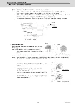
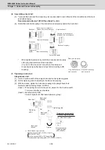
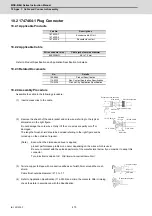
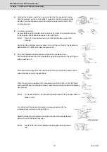
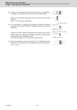
(8) Shift the wire rubber packing and wire clamp to the position in the right figure,
and tighten the wire fixed set screw to fix the cable to receptacle case.
Tighten it not to create the space between the receptacle case and wire fixed
set screw.
(Note)
Confirm that the cable is fixed.
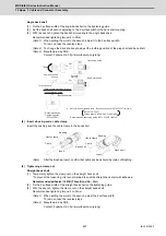
(9) To ensure that there is no leaning on the receptacle housing in the receptacle
case assembly, drop the POST BASE for inspection naturally as shown in the
right figure.
Confirm that the space between the receptacle case assembly and the POST
BASE is within 1mm. Regarding POST BASE for inspection, contact with the
sales department of the manufacturer below.
Tyco Electronics Japan G.K. http://www.te.com/en/home.html
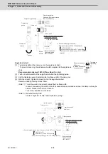
(10) Insert the assembled connector until it stick fast to the POST BASE and then,
tighten the four bind screws to fix. The tightening torque of the bind screw is
5.0 to 10.0 N•cm.
No space
No space
POST BASE for inspection
Receptacle case assembly
1mm MAX
POST BASE for inspection
Receptacle case assembly
Summary of Contents for MDS-E
Page 1: ......
Page 3: ......
Page 15: ......
Page 17: ......
Page 19: ......
Page 21: ......
Page 31: ......
Page 32: ...1 IB 1501229 F 1 Installation ...
Page 76: ...45 IB 1501229 F 2 Wiring and Connection ...
Page 132: ...101 IB 1501229 F 3 Safety Function ...
Page 142: ...111 IB 1501229 F 4 Setup ...
Page 277: ...MDS E EH Series Instruction Manual 4 Setup 246 IB 1501229 F ...
Page 278: ...247 IB 1501229 F 5 Servo Adjustment ...
Page 351: ...MDS E EH Series Instruction Manual 5 Servo Adjustment 320 IB 1501229 F ...
Page 352: ...321 IB 1501229 F 6 Spindle Adjustment ...
Page 404: ...373 IB 1501229 F 7 Troubleshooting ...
Page 455: ...MDS E EH Series Instruction Manual 7 Troubleshooting 424 IB 1501229 F ...
Page 456: ...425 IB 1501229 F 8 Maintenance ...
Page 475: ...MDS E EH Series Instruction Manual 8 Maintenance 444 IB 1501229 F ...
Page 476: ...445 IB 1501229 F 9 Power Backup System ...
Page 494: ...463 IB 1501229 F 10 Appx 1 Cable and Connector Assembly ...
Page 504: ...473 IB 1501229 F 11 Appx 2 D A Output Specifications for Drive Unit ...
Page 514: ...483 IB 1501229 F 12 Appx 3 Protection Function ...
Page 523: ...MDS E EH Series Instruction Manual 12 Appx 3 Protection Function 492 IB 1501229 F ...
Page 524: ...493 IB 1501229 F 13 Appx 4 Compliance to EC Directives ...
Page 528: ...497 IB 1501229 F 14 Appx 5 EMC Installation Guidelines ...
Page 540: ...509 IB 1501229 F 15 Appx 6 Higher Harmonic Suppression Measure Guidelines ...
Page 550: ......
Page 554: ......

