MDS-E/EH Series Instruction Manual
11 Appx. 2: D/A Output Specifications for Drive Unit
475
IB-1501229-F
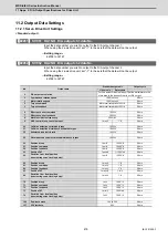
11.2 Output Data Settings
11.2.1 Servo Drive Unit Settings
<Standard output>
【
#2261
】
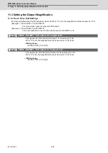
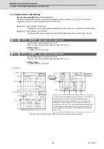
SV061 DA1NO D/A output ch1 data No.
Input the data number you wish to output to the D/A output channel 1.
When using the 2-axis drive unit, set "-1" to the axis that the data will not be output.
---Setting range---
-32768 to 32767
【
#2262
】
SV062 DA2NO D/A output ch2 data No.
Input the data number you wish to output to the D/A output channel 2.
When using the 2-axis drive unit, set "-1" to the axis that the data will not be output.
---Setting range---
-32768 to 32767
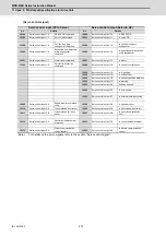
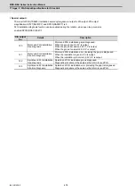
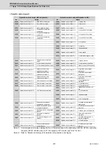
No.
Output data
Standard output unit
Output cycle
Linear axis
Rotary axis
-1
D/A output not selected
For 2nd axis or 3rd axis drive unit.Set the parameters to the
other axes in the drive unit that is not D/A output.
0
Commanded rotation speed
1000(r/min)/V
0.8ms
1
Motor rotation speed
1000(r/min)/V
0.8ms
2
Torque command
Motor stall rated ratio 100%/V
0.8ms
3
Torque feedback
Motor stall rated ratio 100%/V
0.8ms
6
Effective current command
100%/V
0.8ms
7
Effective current feedback
100%/V
0.8ms
8
Machine vibration frequency
500Hz/V
0.8ms
9
HAS control droop cancel amount
1mm/V
1°/V
0.8ms
30
Collision detection estimated torque
100%/V
0.8ms
31
Collision detection disturbance estimated torque
100%/V
0.8ms
32
Estimated load inertia ratio
100%/V
0.8ms
35
Disturbance observer estimated disturbance torque
100%/V
0.8ms
50
Position droop
1
μ
m/V
1/1000°/V
0.8ms
51
Position command
1
μ
m/V
1/1000°/V
0.8ms
52
Position feedback
1
μ
m/V
1/1000°/V
0.8ms
53
Position F
∆
T
1
μ
m/s/V
1/1000°/s/V
0.8ms
54
Deviation from ideal position
(considering servo tracking delay)
1
μ
m/V
1/1000°/V
0.8ms
60
Position droop
1mm/V
1°/V
0.8ms
61
Position command
1mm/V
1°/V
0.8ms
62
Position feedback
1mm/V
1°/V
0.8ms
63
Position F
∆
T
1mm/s/V
1°/s/V
0.8ms
64
Deviation from ideal position
(considering servo tracking delay)
1mm/V
1°/V
0.8ms
70
Position droop
1m/V
1000°/V
0.8ms
71
Position command
1m/V
1000°/V
0.8ms
72
Position feedback
1m/V
1000°/V
0.8ms
73
Position F
∆
T
1m/s/V
1000°/s/V
0.8ms
74
Deviation from ideal position
(considering servo tracking delay)
1m/V
1000°/V
0.8ms
126
Saw tooth wave
1.5V to 3.5V
0.8ms
127
2.5V test data
2.5V
0.8ms
Summary of Contents for MDS-E
Page 1: ......
Page 3: ......
Page 15: ......
Page 17: ......
Page 19: ......
Page 21: ......
Page 31: ......
Page 32: ...1 IB 1501229 F 1 Installation ...
Page 76: ...45 IB 1501229 F 2 Wiring and Connection ...
Page 132: ...101 IB 1501229 F 3 Safety Function ...
Page 142: ...111 IB 1501229 F 4 Setup ...
Page 277: ...MDS E EH Series Instruction Manual 4 Setup 246 IB 1501229 F ...
Page 278: ...247 IB 1501229 F 5 Servo Adjustment ...
Page 351: ...MDS E EH Series Instruction Manual 5 Servo Adjustment 320 IB 1501229 F ...
Page 352: ...321 IB 1501229 F 6 Spindle Adjustment ...
Page 404: ...373 IB 1501229 F 7 Troubleshooting ...
Page 455: ...MDS E EH Series Instruction Manual 7 Troubleshooting 424 IB 1501229 F ...
Page 456: ...425 IB 1501229 F 8 Maintenance ...
Page 475: ...MDS E EH Series Instruction Manual 8 Maintenance 444 IB 1501229 F ...
Page 476: ...445 IB 1501229 F 9 Power Backup System ...
Page 494: ...463 IB 1501229 F 10 Appx 1 Cable and Connector Assembly ...
Page 504: ...473 IB 1501229 F 11 Appx 2 D A Output Specifications for Drive Unit ...
Page 514: ...483 IB 1501229 F 12 Appx 3 Protection Function ...
Page 523: ...MDS E EH Series Instruction Manual 12 Appx 3 Protection Function 492 IB 1501229 F ...
Page 524: ...493 IB 1501229 F 13 Appx 4 Compliance to EC Directives ...
Page 528: ...497 IB 1501229 F 14 Appx 5 EMC Installation Guidelines ...
Page 540: ...509 IB 1501229 F 15 Appx 6 Higher Harmonic Suppression Measure Guidelines ...
Page 550: ......
Page 554: ......

