


MDS-E/EH Series Instruction Manual
12 Appx. 3: Protection Function
488
IB-1501229-F
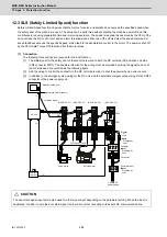
12.3 SLS (Safely Limited Speed) function
Safely Limited Speed function observes that the motors for servo and spindle do not exceed the specified speed when
the safety door of the machine is open. The setup can be performed without shutting the machine power off and this
contributes to reducing preparation time and improving operation. The speed is redundantly observed by the CPU of the
drive unit and the NC control unit, and an alarm is issued when either one of the CPUs detect the speed command or
speed feedback exceeds the specified speed, which lead to the deceleration control in the motor. The power is shut off
by the STO (Safe Torque Off) function after the motor stops.
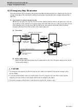
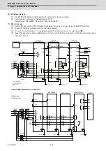
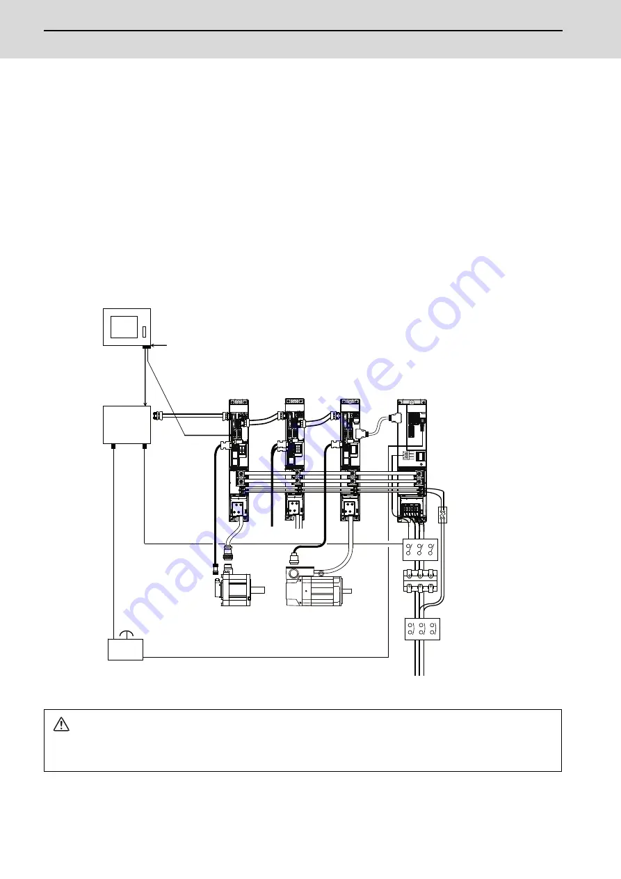
(1) Connection
The following three wirings are required for the SLS function.
[1] The state signal for the safety door of the machine is wired to both the NC unit side (DI) and drive unit side
(CN9 connector MPI1). The double-protection for the wiring must be provided by wiring the signal to each of
the NC side and drive unit side as the following figure.
[2] Add the wiring to control the contactor in the NC unit side in order to shut the power when an error occurs.
[3] In addition to the emergency stop wiring for the NC unit, add the external emergency stop wiring for the CN24
connector of the power supply unit.
CAUTION
The door state signal input port is also used for other signal input depending on the parameter setting. When the input is
duplicated, consider to wire the door state signal to other drive units connecting to the same NC communication line.
L+
L-
MPI1
[1]
[2]
[3]
(MDS-E/EH-CV)
(MDS-E/EH-SP)
(MDS-E/EH-V2)
(MDS-E/EH-V1)
CN24
CN23
Servo motor
Spindle motor
Machine safety door
Open/close switch (
Door status signal
sensor
NC unit
Emergency
stop switch
3-phase AC
power supply
Circuit protector
(Note)
Prepared by
user
AC reactor
Contactor
(Note)
Prepared by
user
Breaker
or
fuse
(Note)
Prepared by
user
To 2th and 3th axis
servo
CN9 connector
)
Summary of Contents for MDS-E
Page 1: ......
Page 3: ......
Page 15: ......
Page 17: ......
Page 19: ......
Page 21: ......
Page 31: ......
Page 32: ...1 IB 1501229 F 1 Installation ...
Page 76: ...45 IB 1501229 F 2 Wiring and Connection ...
Page 132: ...101 IB 1501229 F 3 Safety Function ...
Page 142: ...111 IB 1501229 F 4 Setup ...
Page 277: ...MDS E EH Series Instruction Manual 4 Setup 246 IB 1501229 F ...
Page 278: ...247 IB 1501229 F 5 Servo Adjustment ...
Page 351: ...MDS E EH Series Instruction Manual 5 Servo Adjustment 320 IB 1501229 F ...
Page 352: ...321 IB 1501229 F 6 Spindle Adjustment ...
Page 404: ...373 IB 1501229 F 7 Troubleshooting ...
Page 455: ...MDS E EH Series Instruction Manual 7 Troubleshooting 424 IB 1501229 F ...
Page 456: ...425 IB 1501229 F 8 Maintenance ...
Page 475: ...MDS E EH Series Instruction Manual 8 Maintenance 444 IB 1501229 F ...
Page 476: ...445 IB 1501229 F 9 Power Backup System ...
Page 494: ...463 IB 1501229 F 10 Appx 1 Cable and Connector Assembly ...
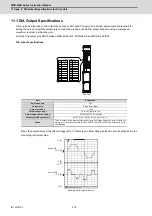
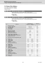
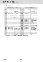
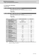
Page 504: ...473 IB 1501229 F 11 Appx 2 D A Output Specifications for Drive Unit ...
Page 514: ...483 IB 1501229 F 12 Appx 3 Protection Function ...
Page 523: ...MDS E EH Series Instruction Manual 12 Appx 3 Protection Function 492 IB 1501229 F ...
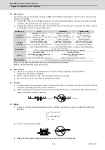
Page 524: ...493 IB 1501229 F 13 Appx 4 Compliance to EC Directives ...
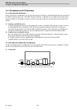
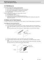
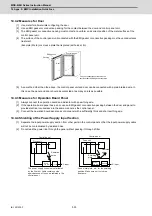
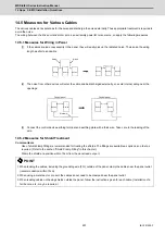
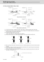
Page 528: ...497 IB 1501229 F 14 Appx 5 EMC Installation Guidelines ...
Page 540: ...509 IB 1501229 F 15 Appx 6 Higher Harmonic Suppression Measure Guidelines ...
Page 550: ......
Page 554: ......


