MDS-E/EH Series Instruction Manual
1 Installation
21
IB-1501229-F
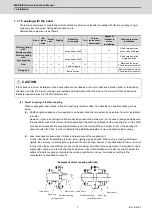
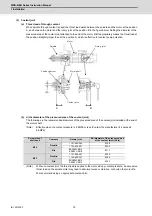
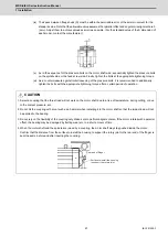
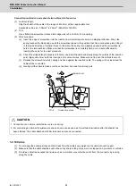
(ix) The space between flange hubs (S) must be within the permissible error of the axial movement for the
standard value. Note that the allowable value assumes that parallel offset and angular misalignment are 0
(zero). Adjust them to achieve values as small as possible. (For the standard value of the S dimension of
each model, contact the manufacturer.)
(x) As in the sequence for the pressure bolts on the motor shaft side, sequentially tighten the pressure bolts
on the spindle side or the feed screw side. Finally, tighten the bolts at the appropriate tightening torque.
(xi) As a countermeasure against initial loosening of the pressure bolts, it is recommended to additionally
tighten the bolts with the appropriate tightening torque after a certain period of operation.
CAUTION
1. Select a coupling that the thrust load will not work on the motor shaft due to a rise of temperature, during cutting, or due
to the coolant pressure, etc.
2. Do not hit the coupling with a tool such as a hammer when installing it to the motor shaft so that the impact load will not
be applied to the bearing.
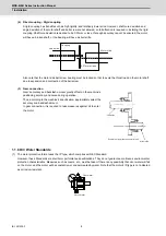
3. Do not rely on the flexibility of the coupling only. Make sure to perform alignment also. If the motor rotates with a parallel
offset, the bearing may be damaged by fretting wear etc. in a short amount of time.
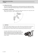
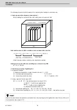
4. When the motor shaft and the spindle are joined by a coupling, the motor shaft may stay pushed inside the motor.
Confirm that the distance from the surface to install the housing to support the rotary joint to the rear end of the flinger is
kept the same before and after inserting the coupling.
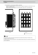
Rear end of flinger
Surface to install the housing
to support the rotary joint
Summary of Contents for MDS-E
Page 1: ......
Page 3: ......
Page 15: ......
Page 17: ......
Page 19: ......
Page 21: ......
Page 31: ......
Page 32: ...1 IB 1501229 F 1 Installation ...
Page 76: ...45 IB 1501229 F 2 Wiring and Connection ...
Page 132: ...101 IB 1501229 F 3 Safety Function ...
Page 142: ...111 IB 1501229 F 4 Setup ...
Page 277: ...MDS E EH Series Instruction Manual 4 Setup 246 IB 1501229 F ...
Page 278: ...247 IB 1501229 F 5 Servo Adjustment ...
Page 351: ...MDS E EH Series Instruction Manual 5 Servo Adjustment 320 IB 1501229 F ...
Page 352: ...321 IB 1501229 F 6 Spindle Adjustment ...
Page 404: ...373 IB 1501229 F 7 Troubleshooting ...
Page 455: ...MDS E EH Series Instruction Manual 7 Troubleshooting 424 IB 1501229 F ...
Page 456: ...425 IB 1501229 F 8 Maintenance ...
Page 475: ...MDS E EH Series Instruction Manual 8 Maintenance 444 IB 1501229 F ...
Page 476: ...445 IB 1501229 F 9 Power Backup System ...
Page 494: ...463 IB 1501229 F 10 Appx 1 Cable and Connector Assembly ...
Page 504: ...473 IB 1501229 F 11 Appx 2 D A Output Specifications for Drive Unit ...
Page 514: ...483 IB 1501229 F 12 Appx 3 Protection Function ...
Page 523: ...MDS E EH Series Instruction Manual 12 Appx 3 Protection Function 492 IB 1501229 F ...
Page 524: ...493 IB 1501229 F 13 Appx 4 Compliance to EC Directives ...
Page 528: ...497 IB 1501229 F 14 Appx 5 EMC Installation Guidelines ...
Page 540: ...509 IB 1501229 F 15 Appx 6 Higher Harmonic Suppression Measure Guidelines ...
Page 550: ......
Page 554: ......

