MDS-E/EH Series Instruction Manual
12 Appx. 3: Protection Function
490
IB-1501229-F
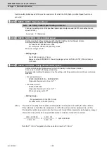
Sets the safely limited speed of the machine and motor for which the SLS (Safely Limited Speed) function is
executed.
【
#2233
】
SV033 SSF2 Servo function 2
bit D : rps Safely limited speed setting increment
Change the setting units of the specified speed signal output speed (SV073) and safely limited
speed (SV238).
0: mm/min 1: 100mm/min
【
#2438
】
SV238 SSCFEED Safely limited speed
Set the machine's safely limited speed for the SLS (Safely Limited Speed) function.
Set this parameter within the following setting ranges.
For linear axis: 2000mm/min or less
For rotary axis: 18000°/min (50r/min) or less
When not using, set to "0".
---Setting range---
0 to 18000 (mm/min) or (°/min)
However, when SV033/bitD=1, the setting range is from -32768 to 32767 (100 mm/min) or
(100°/min).
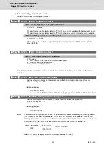
【
#2439
】
SV239 SSCRPM Safely limited motor speed
Set the motor's safely limited speed for the SLS (Safely Limited Speed) function.
Set a value to hold the following relationship.
Be aware when setting the parameter as the setting units for general motors and linear motors are
different.
<<For general motor>>
SV239=(SV238/SV018) × (SV002/SV001)
Only when the product is 0, set to "1".
<<For linear motor>>
SV239=SV238/60
Only when the product is 0, set to "1".
When not using, set to "0".
---Setting range---
For general motor:0 to 32767 (r/min)
For linear motor: 0 to 32767 (mm/s)
(Note)
The value of the safely limited speed and safely limited motor speed must satisfy the above relation.
If this relation is not satisfied, the parameter error (37or E4) will occur.(Error parameter No. is 239.)
Checking this relation is executed when the drive unit is turned ON and parameter is changed and speed
observation mode (states when a speed observation command is turned ON) is entered.
Note that "1 (r/min)" is applied when the calculation result is "0 (r/min)"
SV238 :SSCFEED
SV002 :PC2
SV018 :PIT
X
SV001 :PC1
=
SV239 :SSCRPM
Summary of Contents for MDS-E
Page 1: ......
Page 3: ......
Page 15: ......
Page 17: ......
Page 19: ......
Page 21: ......
Page 31: ......
Page 32: ...1 IB 1501229 F 1 Installation ...
Page 76: ...45 IB 1501229 F 2 Wiring and Connection ...
Page 132: ...101 IB 1501229 F 3 Safety Function ...
Page 142: ...111 IB 1501229 F 4 Setup ...
Page 277: ...MDS E EH Series Instruction Manual 4 Setup 246 IB 1501229 F ...
Page 278: ...247 IB 1501229 F 5 Servo Adjustment ...
Page 351: ...MDS E EH Series Instruction Manual 5 Servo Adjustment 320 IB 1501229 F ...
Page 352: ...321 IB 1501229 F 6 Spindle Adjustment ...
Page 404: ...373 IB 1501229 F 7 Troubleshooting ...
Page 455: ...MDS E EH Series Instruction Manual 7 Troubleshooting 424 IB 1501229 F ...
Page 456: ...425 IB 1501229 F 8 Maintenance ...
Page 475: ...MDS E EH Series Instruction Manual 8 Maintenance 444 IB 1501229 F ...
Page 476: ...445 IB 1501229 F 9 Power Backup System ...
Page 494: ...463 IB 1501229 F 10 Appx 1 Cable and Connector Assembly ...
Page 504: ...473 IB 1501229 F 11 Appx 2 D A Output Specifications for Drive Unit ...
Page 514: ...483 IB 1501229 F 12 Appx 3 Protection Function ...
Page 523: ...MDS E EH Series Instruction Manual 12 Appx 3 Protection Function 492 IB 1501229 F ...
Page 524: ...493 IB 1501229 F 13 Appx 4 Compliance to EC Directives ...
Page 528: ...497 IB 1501229 F 14 Appx 5 EMC Installation Guidelines ...
Page 540: ...509 IB 1501229 F 15 Appx 6 Higher Harmonic Suppression Measure Guidelines ...
Page 550: ......
Page 554: ......

