


MDS-E/EH Series Instruction Manual
13 Appx. 4: Compliance to EC Directives
494
IB-1501229-F
13.1 Compliance to EC Directives
13.1.1 European EC Directives
In the EU Community, the attachment of a CE mark (CE marking) is mandatory to indicate that the basic safety conditions of
the Machine Directives (issued Jan. 1995), EMC Directives (issued Jan. 1996) and the Low-voltage Directives (issued Jan.
1997) are satisfied. The machines and devices in which the servo and spindle drive are assembled are the targets for CE
marking.
(1) Compliance to EMC Directives
The servo and spindle drive are components designed to be used in combination with a machine or device. These are
not directly targeted by the Directives, but a CE mark must be attached to machines and devices in which these
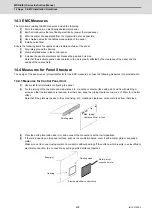
components are assembled. The next section "EMC Installation Guidelines", which explains the unit installation and
control panel manufacturing method, etc., has been prepared to make compliance to the EMC Directives easier.
(2) Compliance to Low-voltage Directives
Each unit is targeted for the Low-voltage Directives. An excerpt of the precautions given in this specification is given
below. Please read this section thoroughly before starting use.
For the EMC Directives and Low-voltage Directives, Self-Declaration Documents has been prepared.
Contact Mitsubishi or your dealer when required.
13.1.2 Cautions for EC Directive Compliance
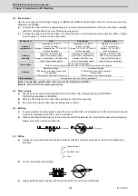
Use the Low-voltage Directive compatible parts for the servo/spindle drive and servo/spindle motor. In addition to the items
described in this instruction manual, observe the items described below.
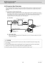
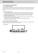
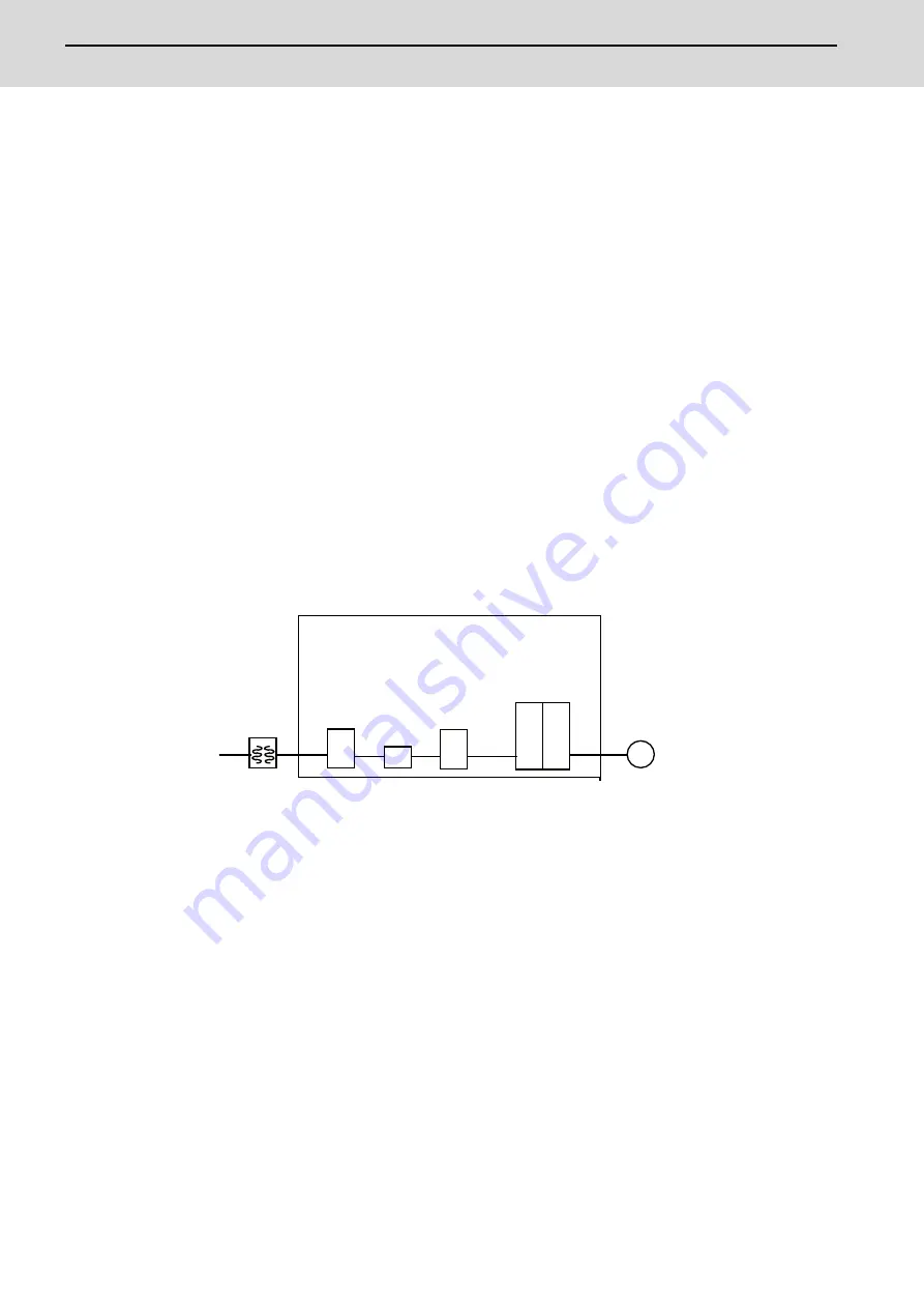
(1) Configuration
CB MC
M
Circuit breaker
Insert a type B circuit breaker (RCD) in the power supply side of the unit.
Isolating
transformer
AC reactor
Electromagnetic
contactor
Unit
Summary of Contents for MDS-E
Page 1: ......
Page 3: ......
Page 15: ......
Page 17: ......
Page 19: ......
Page 21: ......
Page 31: ......
Page 32: ...1 IB 1501229 F 1 Installation ...
Page 76: ...45 IB 1501229 F 2 Wiring and Connection ...
Page 132: ...101 IB 1501229 F 3 Safety Function ...
Page 142: ...111 IB 1501229 F 4 Setup ...
Page 277: ...MDS E EH Series Instruction Manual 4 Setup 246 IB 1501229 F ...
Page 278: ...247 IB 1501229 F 5 Servo Adjustment ...
Page 351: ...MDS E EH Series Instruction Manual 5 Servo Adjustment 320 IB 1501229 F ...
Page 352: ...321 IB 1501229 F 6 Spindle Adjustment ...
Page 404: ...373 IB 1501229 F 7 Troubleshooting ...
Page 455: ...MDS E EH Series Instruction Manual 7 Troubleshooting 424 IB 1501229 F ...
Page 456: ...425 IB 1501229 F 8 Maintenance ...
Page 475: ...MDS E EH Series Instruction Manual 8 Maintenance 444 IB 1501229 F ...
Page 476: ...445 IB 1501229 F 9 Power Backup System ...
Page 494: ...463 IB 1501229 F 10 Appx 1 Cable and Connector Assembly ...
Page 504: ...473 IB 1501229 F 11 Appx 2 D A Output Specifications for Drive Unit ...
Page 514: ...483 IB 1501229 F 12 Appx 3 Protection Function ...
Page 523: ...MDS E EH Series Instruction Manual 12 Appx 3 Protection Function 492 IB 1501229 F ...
Page 524: ...493 IB 1501229 F 13 Appx 4 Compliance to EC Directives ...
Page 528: ...497 IB 1501229 F 14 Appx 5 EMC Installation Guidelines ...
Page 540: ...509 IB 1501229 F 15 Appx 6 Higher Harmonic Suppression Measure Guidelines ...
Page 550: ......
Page 554: ......


