


MDS-E/EH Series Instruction Manual
14 Appx. 5: EMC Installation Guidelines
501
IB-1501229-F
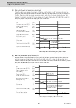
14.5 Measures for Various Cables
The various cables act as antennas for the noise and discharge the noise externally. Thus appropriate treatment is required to
avoid the noise.
The wiring between the drive unit and motor act as an extremely powerful noise source, so apply the following measures.
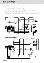
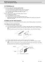
14.5.1 Measures for Wiring in Panel
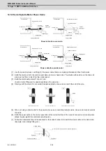
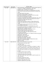
[1] If the cables are led unnecessarily in the panel, they will easily pick up the radiated noise. Thus, keep the wiring
length as short as possible.
[2] The noise from other devices will enter the cable and be discharged externally, so avoid internal wiring near the
openings.
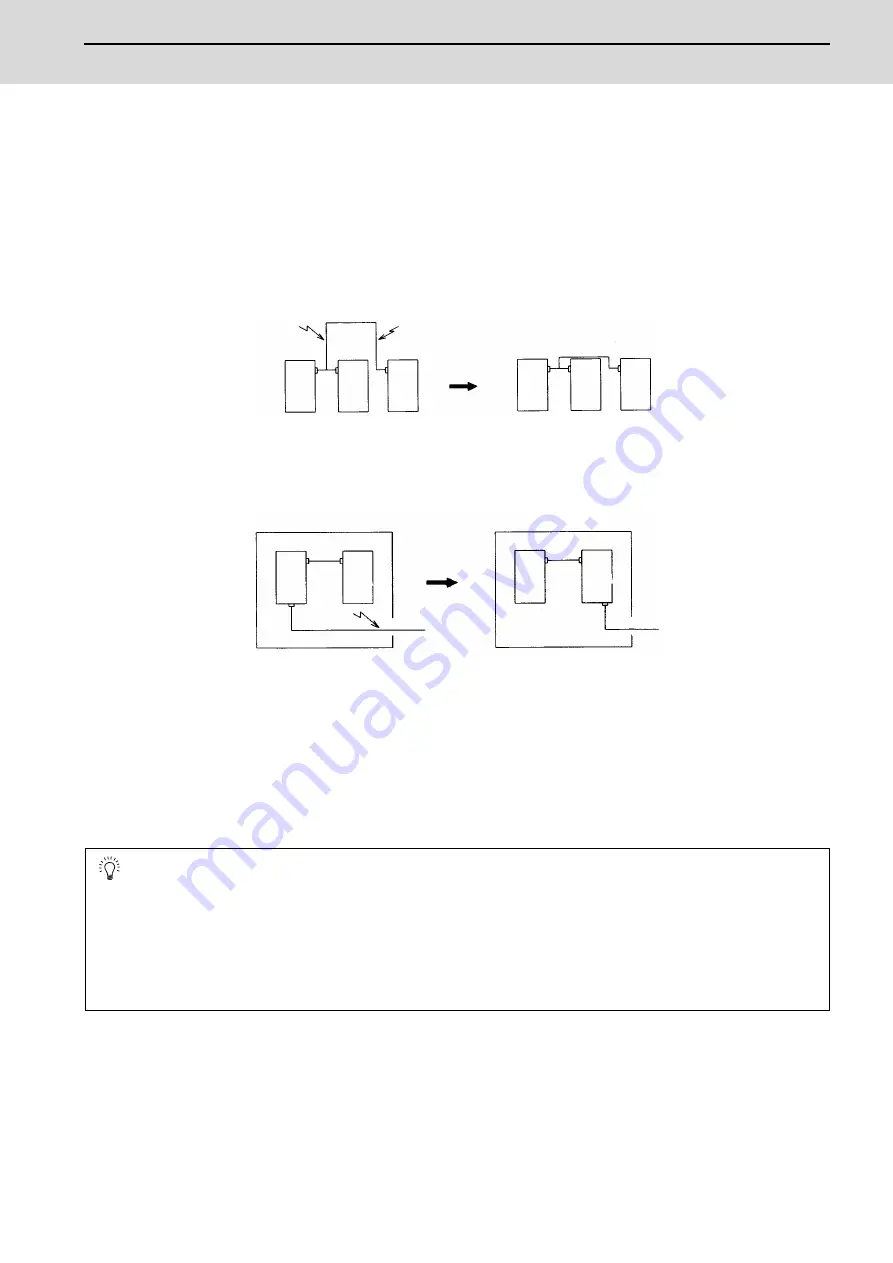
[3] Connect the control device earthing terminal and earthing plate with a thick wire. Take care to the leading of the
wire.
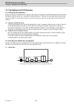
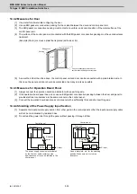
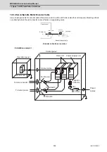
14.5.2 Measures for Shield Treatment
Common items
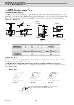
Use of shield clamp fittings is recommended for treating the shields. The fittings are available as options, so order as
required. (Refer to the section "Shield Clamp Fitting" in this chapter.)
Clamp the shield at a position within 10cm from the panel lead out port.
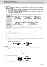
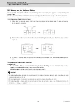
POINT
1. When leading the cables, including the grounding wire (FG), outside of the panel, clamp the cables near the panel outlet
(recommendation: within 10cm).
2. When using a metal duct or conduit, the cables do not need to be clamped near the panel outlet.
3. When leading cables not having shields outside the panel, follow the instructions given for each cable. (Installation of a
ferrite core, etc., may be required.)
Device
Device
Device
Device
Device
Device
Noise
Noise
Noise
Device
Device
Device
Device
Control panel
Control panel
Summary of Contents for MDS-E
Page 1: ......
Page 3: ......
Page 15: ......
Page 17: ......
Page 19: ......
Page 21: ......
Page 31: ......
Page 32: ...1 IB 1501229 F 1 Installation ...
Page 76: ...45 IB 1501229 F 2 Wiring and Connection ...
Page 132: ...101 IB 1501229 F 3 Safety Function ...
Page 142: ...111 IB 1501229 F 4 Setup ...
Page 277: ...MDS E EH Series Instruction Manual 4 Setup 246 IB 1501229 F ...
Page 278: ...247 IB 1501229 F 5 Servo Adjustment ...
Page 351: ...MDS E EH Series Instruction Manual 5 Servo Adjustment 320 IB 1501229 F ...
Page 352: ...321 IB 1501229 F 6 Spindle Adjustment ...
Page 404: ...373 IB 1501229 F 7 Troubleshooting ...
Page 455: ...MDS E EH Series Instruction Manual 7 Troubleshooting 424 IB 1501229 F ...
Page 456: ...425 IB 1501229 F 8 Maintenance ...
Page 475: ...MDS E EH Series Instruction Manual 8 Maintenance 444 IB 1501229 F ...
Page 476: ...445 IB 1501229 F 9 Power Backup System ...
Page 494: ...463 IB 1501229 F 10 Appx 1 Cable and Connector Assembly ...
Page 504: ...473 IB 1501229 F 11 Appx 2 D A Output Specifications for Drive Unit ...
Page 514: ...483 IB 1501229 F 12 Appx 3 Protection Function ...
Page 523: ...MDS E EH Series Instruction Manual 12 Appx 3 Protection Function 492 IB 1501229 F ...
Page 524: ...493 IB 1501229 F 13 Appx 4 Compliance to EC Directives ...
Page 528: ...497 IB 1501229 F 14 Appx 5 EMC Installation Guidelines ...
Page 540: ...509 IB 1501229 F 15 Appx 6 Higher Harmonic Suppression Measure Guidelines ...
Page 550: ......
Page 554: ......


