MDS-E/EH Series Instruction Manual
14 Appx. 5: EMC Installation Guidelines
504
IB-1501229-F
14.6 EMC Countermeasure Parts
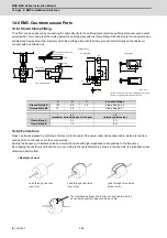
14.6.1 Shield Clamp Fitting
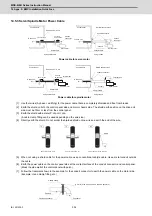
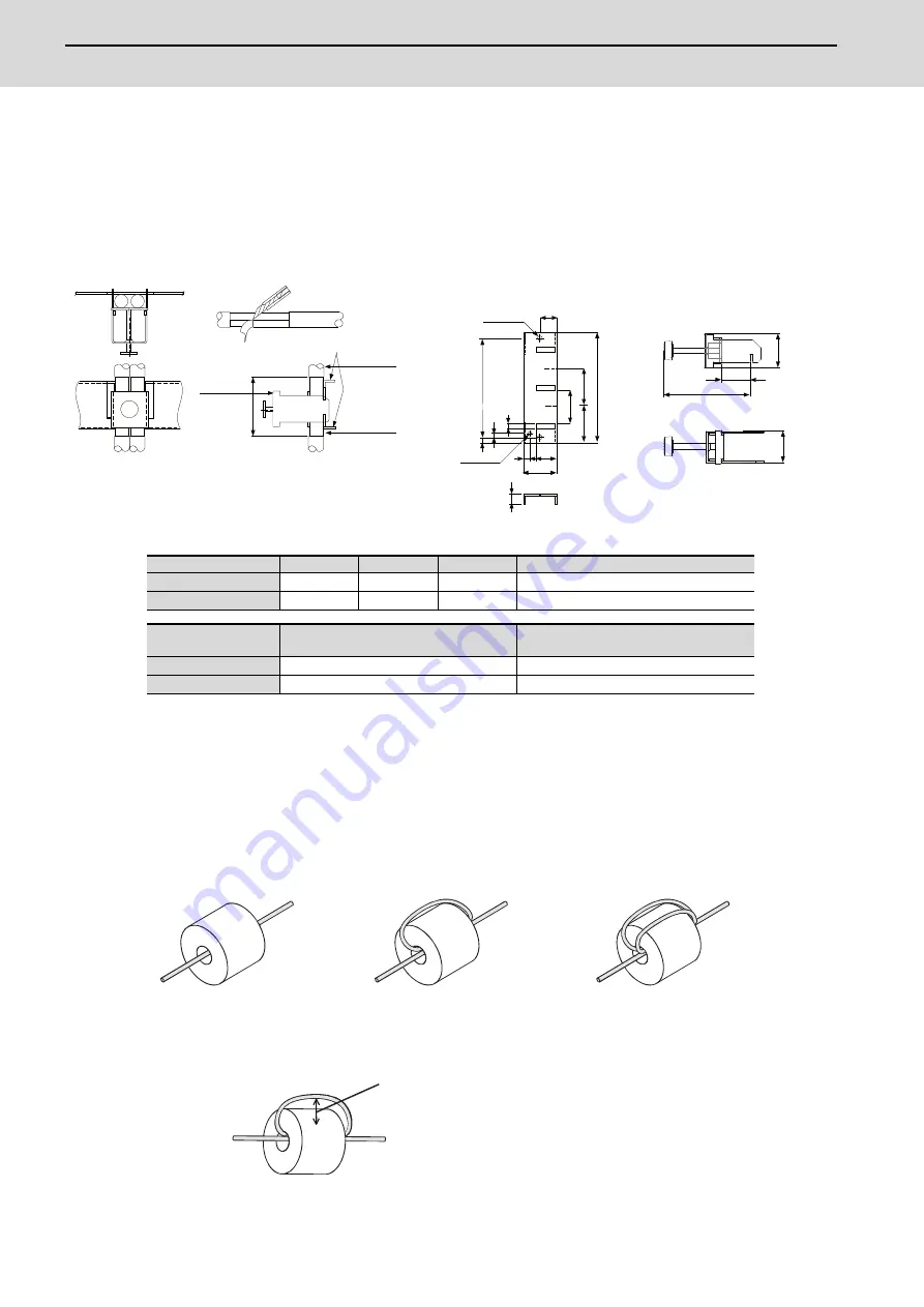
The effect can be enhanced by connecting the cable directly to the earthing plate. Install an earthing plate near each panel's
outlet (within 10cm), and press the cable against the earthing plate with the clamp fitting. If the cables are thin, several can be
bundled and clamped together. Securely earth the earthing plate with the frame ground. Install directly on the cabinet or
connect with an earthing wire.
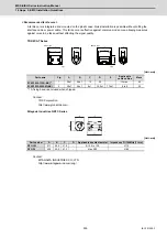
14.6.2 Ferrite Core
Noise can be suppressed by installing a ferrite core to the cable if the power cable and encoder cable, which are led from
outside of the control panel, are the noise sources.
Specify the frequency of radiated noise and select the ferrite with high impedance corresponding to the frequency.
By wrapping the cable around the ferrite core according to the cable diameter as shown in the example, the impedance rises,
obtaining a better effect.
< Example of use >
A
B
C
Enclosed fittings
Ground Plate #D
100
86
30
Clamp fitting A x 2
Ground Plate #E
70
56
-
Clamp fitting B x 1
L1
(maximum dimension when it is open)
L2
(reference dimension)
Clamp fitting A
25
(77)
Clamp fitting B
12
(54)
4
0
35
6
22
17.5
A
C
3
5
2
4
-
0
.2
0
1
1
7
3
6
B
±
0
.3
L1
3
0
L2
+
0
.3 0
2
4
2-
ȭ
[Unit: mm]
(Note 1) Screw hole for wiring to earthing plate in cabinet.
(Note 2) The earthing plate thickness is 1.6mm.
hole
(Fitting A, B)
Installation hole
Clamp fitting
Earthing plate
࣭
Outline drawing
5
M4 screw
1RWH
Shield sheath
Cable
Cable
Earthing plate
Peel the cable sheath at the
clamp section.
View of clamp section
Clamp fitting
Lead through one time
(one turn)
Lead through two times
(two turns)
Lead through three times
(three turns)
The clearance between the ferrite core and cable must be
as narrow as possible when winding a cable.
Summary of Contents for MDS-E
Page 1: ......
Page 3: ......
Page 15: ......
Page 17: ......
Page 19: ......
Page 21: ......
Page 31: ......
Page 32: ...1 IB 1501229 F 1 Installation ...
Page 76: ...45 IB 1501229 F 2 Wiring and Connection ...
Page 132: ...101 IB 1501229 F 3 Safety Function ...
Page 142: ...111 IB 1501229 F 4 Setup ...
Page 277: ...MDS E EH Series Instruction Manual 4 Setup 246 IB 1501229 F ...
Page 278: ...247 IB 1501229 F 5 Servo Adjustment ...
Page 351: ...MDS E EH Series Instruction Manual 5 Servo Adjustment 320 IB 1501229 F ...
Page 352: ...321 IB 1501229 F 6 Spindle Adjustment ...
Page 404: ...373 IB 1501229 F 7 Troubleshooting ...
Page 455: ...MDS E EH Series Instruction Manual 7 Troubleshooting 424 IB 1501229 F ...
Page 456: ...425 IB 1501229 F 8 Maintenance ...
Page 475: ...MDS E EH Series Instruction Manual 8 Maintenance 444 IB 1501229 F ...
Page 476: ...445 IB 1501229 F 9 Power Backup System ...
Page 494: ...463 IB 1501229 F 10 Appx 1 Cable and Connector Assembly ...
Page 504: ...473 IB 1501229 F 11 Appx 2 D A Output Specifications for Drive Unit ...
Page 514: ...483 IB 1501229 F 12 Appx 3 Protection Function ...
Page 523: ...MDS E EH Series Instruction Manual 12 Appx 3 Protection Function 492 IB 1501229 F ...
Page 524: ...493 IB 1501229 F 13 Appx 4 Compliance to EC Directives ...
Page 528: ...497 IB 1501229 F 14 Appx 5 EMC Installation Guidelines ...
Page 540: ...509 IB 1501229 F 15 Appx 6 Higher Harmonic Suppression Measure Guidelines ...
Page 550: ......
Page 554: ......

