MDS-E/EH Series Instruction Manual
14 Appx. 5: EMC Installation Guidelines
508
IB-1501229-F
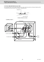
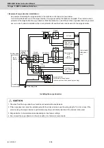
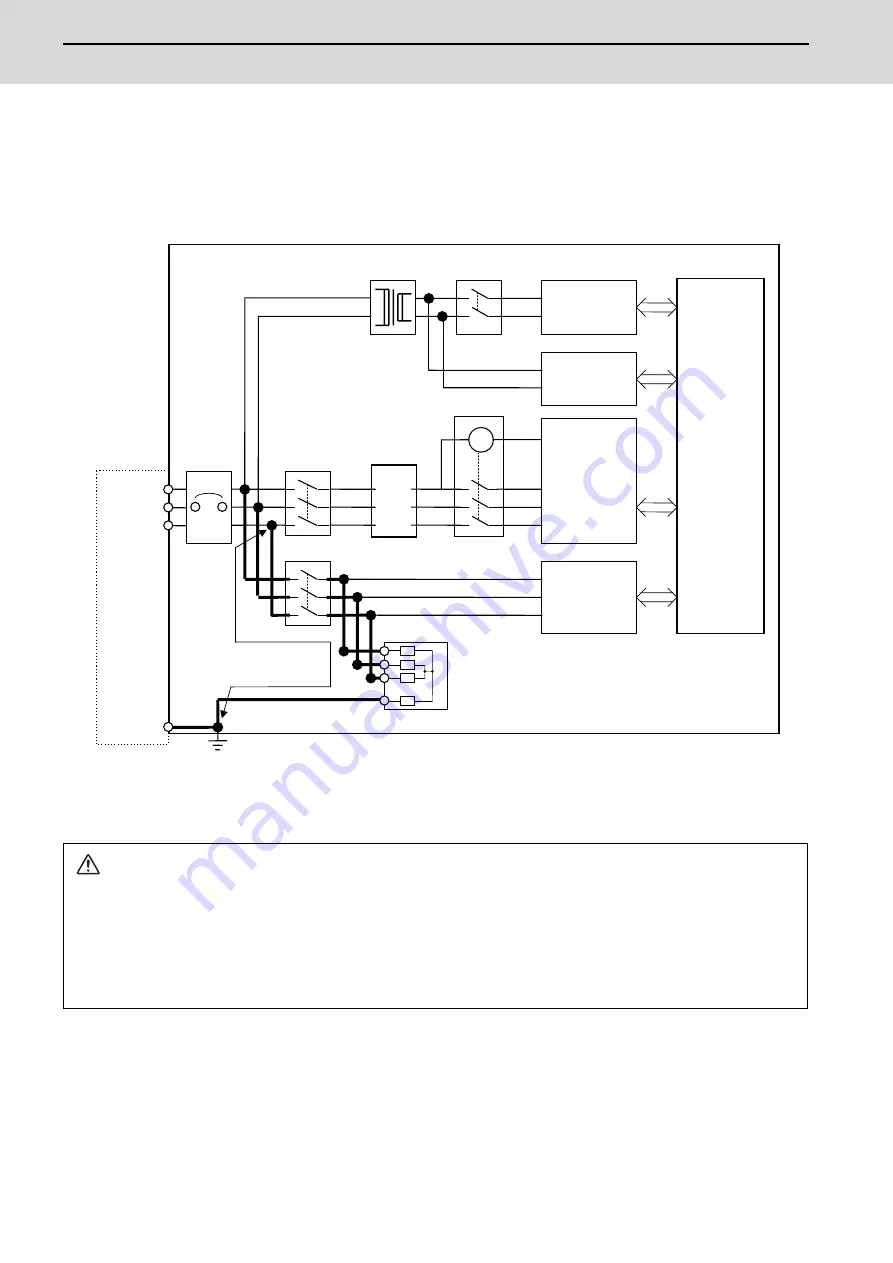
< Example of surge absorber installation >
An example of installing the surge absorber in the machine control panel is shown below.
A short-circuit fault will occur in the surge absorber if a surge exceeding the tolerance is applied. Thus, install a circuit
protector in the stage before the surge absorber. Note that almost no current flows to the surge absorber during normal
use, so a circuit protector installed as the circuit protection for another device can be used for the surge absorber.
Installing the surge absorber
CAUTION
1. The wires from the surge absorber should be connected without extensions.
2. If the surge absorber cannot be installed just with the enclosed wires, keep the wiring length of A to 2m or less. If the
wires are long, the surge absorber's performance may drop and inhibit protection of the devices in the panel.
3. Surge absorber to be selected varies depending on input power voltage.
4. Do not insert the surge absorber in the place with a lot of harmonic components.
A
MC
Circuit
protector
NC unit
Control panel
(relay panel,
etc.)
Other device
(panel power
supply, etc.)
Other device
(panel power
supply, etc.)
Panel earth
leakage
breaker
Input
power
Circuit
protector
AC reactor
Transformer
Grounding
Grounding plate
Factory power
Contactor
Circuit
protector
Power supply
unit
and
drive unit
Surge absorber
(Protection across phases/
Protection across each phase’s grounding)
Summary of Contents for MDS-E
Page 1: ......
Page 3: ......
Page 15: ......
Page 17: ......
Page 19: ......
Page 21: ......
Page 31: ......
Page 32: ...1 IB 1501229 F 1 Installation ...
Page 76: ...45 IB 1501229 F 2 Wiring and Connection ...
Page 132: ...101 IB 1501229 F 3 Safety Function ...
Page 142: ...111 IB 1501229 F 4 Setup ...
Page 277: ...MDS E EH Series Instruction Manual 4 Setup 246 IB 1501229 F ...
Page 278: ...247 IB 1501229 F 5 Servo Adjustment ...
Page 351: ...MDS E EH Series Instruction Manual 5 Servo Adjustment 320 IB 1501229 F ...
Page 352: ...321 IB 1501229 F 6 Spindle Adjustment ...
Page 404: ...373 IB 1501229 F 7 Troubleshooting ...
Page 455: ...MDS E EH Series Instruction Manual 7 Troubleshooting 424 IB 1501229 F ...
Page 456: ...425 IB 1501229 F 8 Maintenance ...
Page 475: ...MDS E EH Series Instruction Manual 8 Maintenance 444 IB 1501229 F ...
Page 476: ...445 IB 1501229 F 9 Power Backup System ...
Page 494: ...463 IB 1501229 F 10 Appx 1 Cable and Connector Assembly ...
Page 504: ...473 IB 1501229 F 11 Appx 2 D A Output Specifications for Drive Unit ...
Page 514: ...483 IB 1501229 F 12 Appx 3 Protection Function ...
Page 523: ...MDS E EH Series Instruction Manual 12 Appx 3 Protection Function 492 IB 1501229 F ...
Page 524: ...493 IB 1501229 F 13 Appx 4 Compliance to EC Directives ...
Page 528: ...497 IB 1501229 F 14 Appx 5 EMC Installation Guidelines ...
Page 540: ...509 IB 1501229 F 15 Appx 6 Higher Harmonic Suppression Measure Guidelines ...
Page 550: ......
Page 554: ......

