MDS-E/EH Series Instruction Manual
1 Installation
23
IB-1501229-F
1.2.9 Connection
(1) Cable wiring
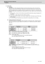
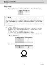
When connecting the power line to the terminal block, tighten the screws with proper torque as shown below.
(2) Connection of conduit connector
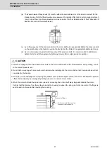
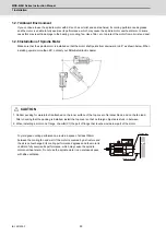
When installing a connector to a terminal box, select a water proof connector with rubber packing and prevent
conductive foreign matter and other combustible foreign matter from entering through the wiring hole on the
terminal box.
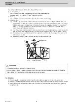
Use a smaller nut than the following size to fix the connector on the terminal box.
For the wiring hole diameter, refer to "DRIVE SYSTEM DATA BOOK (IB-1501252)".
Prepare a bushing, nut, and O-ring when using a connector smaller than the wiring hole on the terminal box.
SJ-V/SJ-VL/SJ-PMF/SJ-4-V Series
SJ-D/DJ/DL/DG/DN Series
Screw size
Proper torque [N•m]
M4
2.0
M5
2.5
M6
3.0
M8
10.0
CAUTION
1. When connecting the power line to the terminal block, tighten the screws with proper torque described in this section.
2. Make sure to connect the terminal to the terminal block. If running the motor with the terminal loosened, fires could be
caused by motor overheat, and earth fault, short circuit and electric shocks could be caused by disconnection of the
terminal.
3.To keep the insulation distance, always cover crimp terminals with insulation tubes when connecting crimp terminals at
the end of the power line.
Wiring hole diameter [mm]
Outer diameter [mm]
Φ
35
Φ
58
Φ
44
Φ
58
Φ
51
Φ
93
Φ
61
Φ
93
Φ
63
Φ
93
Wiring hole diameter [mm]
Outer diameter [mm]
Φ
44
Φ
56
Φ
61
Φ
80
Outer diameter
Summary of Contents for MDS-E
Page 1: ......
Page 3: ......
Page 15: ......
Page 17: ......
Page 19: ......
Page 21: ......
Page 31: ......
Page 32: ...1 IB 1501229 F 1 Installation ...
Page 76: ...45 IB 1501229 F 2 Wiring and Connection ...
Page 132: ...101 IB 1501229 F 3 Safety Function ...
Page 142: ...111 IB 1501229 F 4 Setup ...
Page 277: ...MDS E EH Series Instruction Manual 4 Setup 246 IB 1501229 F ...
Page 278: ...247 IB 1501229 F 5 Servo Adjustment ...
Page 351: ...MDS E EH Series Instruction Manual 5 Servo Adjustment 320 IB 1501229 F ...
Page 352: ...321 IB 1501229 F 6 Spindle Adjustment ...
Page 404: ...373 IB 1501229 F 7 Troubleshooting ...
Page 455: ...MDS E EH Series Instruction Manual 7 Troubleshooting 424 IB 1501229 F ...
Page 456: ...425 IB 1501229 F 8 Maintenance ...
Page 475: ...MDS E EH Series Instruction Manual 8 Maintenance 444 IB 1501229 F ...
Page 476: ...445 IB 1501229 F 9 Power Backup System ...
Page 494: ...463 IB 1501229 F 10 Appx 1 Cable and Connector Assembly ...
Page 504: ...473 IB 1501229 F 11 Appx 2 D A Output Specifications for Drive Unit ...
Page 514: ...483 IB 1501229 F 12 Appx 3 Protection Function ...
Page 523: ...MDS E EH Series Instruction Manual 12 Appx 3 Protection Function 492 IB 1501229 F ...
Page 524: ...493 IB 1501229 F 13 Appx 4 Compliance to EC Directives ...
Page 528: ...497 IB 1501229 F 14 Appx 5 EMC Installation Guidelines ...
Page 540: ...509 IB 1501229 F 15 Appx 6 Higher Harmonic Suppression Measure Guidelines ...
Page 550: ......
Page 554: ......

