MDS-E/EH Series Instruction Manual
15 Appx. 6: Higher Harmonic Suppression Measure Guidelines
511
IB-1501229-F
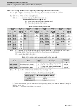
15.1.1 Calculating the Equivalent Capacity of the Higher Harmonic Generator
As a principle, the higher harmonic suppression measure guidelines must be followed by the customer.
(1) Calculating the total equivalent capacity (Step 1)
Calculate the total equivalent capacity with the following expression.
Total equivalent circuit: Po =
Σ
• Ki • Pi
Ki
:Conversion coefficient (Refer to following table)
Pi
:Rated input capacity of each device
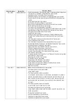
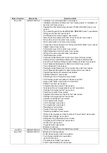
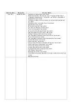
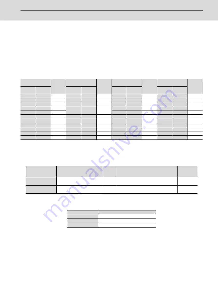
(Table 1) Rated capacity of each unit
(Note)
The rated capacity Pi above, is the value used to calculate whether the product corresponds to the higher
harmonic guidelines. Thus, the value will differ from the actual power facility's capacity.
(The power supply unit is not included.)
(Table 2) Circuit class and conversion coefficient for each unit
(Note)
This applies when an AC reactor is installed on the power supply unit.
(Table 3) Limit values for total equivalent capacity
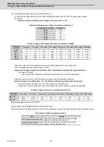
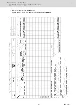
If the total equivalent capacity Po exceeds the limit value given in (Table 3), proceed to "(2) Calculating the higher
harmonic current flow".
Measures are not required if the value is not exceeded.
Unit type
MDS-
Rated
input
capacity
pi [kVA]
Unit type
MDS-
Rated
input
capacity
pi [kVA]
Unit type
MDS-
Rated
input
capacity
pi [kVA]
Unit type
MDS-
Rated
input
capacity
pi [kVA]
E-
EH-
E-
EH-
E-
EH-
E-
EH-
SP-20
-
0.97
SP2-20
-
1.94
V1-20
V1-10
1.0
V2-20
V2-10
2.0
SP-40
SP-20
2.81
SP2-40
-
5.62
V1-40
V1-20
1.6
V2-40
V2-20
3.2
SP-80
SP-40
6.77
SP2-80
-
13.54
V1-80
V1-40
2.7
V2-80
V2-40
5.4
SP-160
SP-80
13.1
SP2-
16080
-
15.84
V1-160
V1-80
5.9
V2-160
V2-80
11.8
SP-200
SP-100
21.8
V1-160W V1-80W
9
V2-160W V2-80W
18.0
SP-240
-
25.9
V1-320
V1-160
11.5
-
V2-160
23.0
SP-320
SP-160
34.7
V1-320W V1-160W
13.1
V3-20
-
3.0
SP-400
SP-200
42.8
V1-200
21.7
V3-40
-
4.8
SP-640
SP-320
63.7
SP-480
86.8
SP-600
120.2
Name
Model
Circuit
class
Circuit type
Conversion
coefficient
Ki
Servo drive unit
MDS-E/EH-V1/V2/V3 Series
3
3-phase bridge (with smoothing capacitor)
With AC reactor (Note 1)
K32=1.8
Spindle drive unit
MDS-E/EH-SP/SP2 Series
3
3-phase bridge (with smoothing capacitor)
With AC reactor (Note 1)
K32=1.8
Incoming voltage
Total of 6-pulse equivalent capacity
6.6kV
50kVA
22/33kV
300kVA
66kV or more
2,000kVA
Summary of Contents for MDS-E
Page 1: ......
Page 3: ......
Page 15: ......
Page 17: ......
Page 19: ......
Page 21: ......
Page 31: ......
Page 32: ...1 IB 1501229 F 1 Installation ...
Page 76: ...45 IB 1501229 F 2 Wiring and Connection ...
Page 132: ...101 IB 1501229 F 3 Safety Function ...
Page 142: ...111 IB 1501229 F 4 Setup ...
Page 277: ...MDS E EH Series Instruction Manual 4 Setup 246 IB 1501229 F ...
Page 278: ...247 IB 1501229 F 5 Servo Adjustment ...
Page 351: ...MDS E EH Series Instruction Manual 5 Servo Adjustment 320 IB 1501229 F ...
Page 352: ...321 IB 1501229 F 6 Spindle Adjustment ...
Page 404: ...373 IB 1501229 F 7 Troubleshooting ...
Page 455: ...MDS E EH Series Instruction Manual 7 Troubleshooting 424 IB 1501229 F ...
Page 456: ...425 IB 1501229 F 8 Maintenance ...
Page 475: ...MDS E EH Series Instruction Manual 8 Maintenance 444 IB 1501229 F ...
Page 476: ...445 IB 1501229 F 9 Power Backup System ...
Page 494: ...463 IB 1501229 F 10 Appx 1 Cable and Connector Assembly ...
Page 504: ...473 IB 1501229 F 11 Appx 2 D A Output Specifications for Drive Unit ...
Page 514: ...483 IB 1501229 F 12 Appx 3 Protection Function ...
Page 523: ...MDS E EH Series Instruction Manual 12 Appx 3 Protection Function 492 IB 1501229 F ...
Page 524: ...493 IB 1501229 F 13 Appx 4 Compliance to EC Directives ...
Page 528: ...497 IB 1501229 F 14 Appx 5 EMC Installation Guidelines ...
Page 540: ...509 IB 1501229 F 15 Appx 6 Higher Harmonic Suppression Measure Guidelines ...
Page 550: ......
Page 554: ......


