MDS-E/EH Series Instruction Manual
15 Appx. 6: Higher Harmonic Suppression Measure Guidelines
512
IB-1501229-F
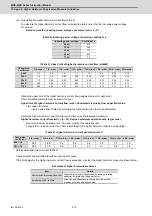
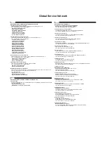
(2) Calculating the higher harmonic current flow (Step 2)
To calculate the higher harmonic current flow, calculate the rated current for the incoming power voltage
conversion.
Rated current for incoming power voltage conversion (mA) = a • Pi
(Table 4) Incoming power voltage conversion coefficient a
(Table 5) Upper limit of higher harmonic current flow (mA/kW)
Obtain the upper limit of the higher harmonic current flow (judgment value) for each order.
(The contracted electricity must be known for this.)
Upper limit of higher harmonic current flow (mA) = Contracted electricity, flow upper limit value
Flow upper limit value :
Insert a value from Table 5 according to the higher harmonic order to be calculated.
Obtain the higher harmonic current flow for each order using the following expression.
Higher harmonic current flow (mA) = (a • Pi), Device's maximum operation rate, target order
Device's maximum operation rate : The user must set the operation rate.
Target order : Insert a value from Table 6 according to the higher harmonic order to be calculated.
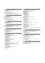
(Table 6) Higher harmonic current generation rate %
Values when basic wave current is 100%.
Check whether the calculated results exceed the limit value.
If the limit value for the higher harmonic current flow is exceeded, consider the higher harmonic measures shown below.
Examples of higher harmonic measures
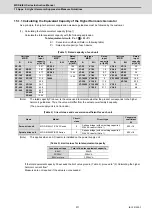
Incoming power voltage
Coefficient a
6.6kV
87.5
22 kV
26.2
33 kV
17.5
66 kV
8.75
77 kV
7.5
Conversion
coefficient
5th- order
7th- order
11th- order 13th- order 17th- order 19th- order 23rd- order 25th- order
6.6kV
3.5
2.5
1.6
1.3
1.0
0.9
0.76
0.70
22kV
1.8
1.3
0.82
0.69
0.53
0.47
0.39
0.36
33kV
1.2
0.86
0.55
0.46
0.35
0.32
0.26
0.24
66kV
0.59
0.42
0.27
0.23
0.17
0.16
0.13
0.12
77kV
0.50
0.36
0.23
0.19
0.15
0.13
0.11
0.10
Conversion
coefficient
5th- order
7th- order
11th- order
13th- order
17th- order
19th- order
23rd- order
25th- order
K32 = 1.8
38.0
14.5
7.4
3.4
3.2
1.9
1.7
1.3
K31 = 3.4
65.0
41.0
8.5
7.7
4.3
3.1
2.6
1.8
Item
Details
Power-factor improving capacitor
Higher harmonics are suppressed by adding a leading
capacitor for improving the power factor.
Installation of AC line filter
A reactor and capacitor are combined to reduce the
impedance for specific frequencies.
Summary of Contents for MDS-E
Page 1: ......
Page 3: ......
Page 15: ......
Page 17: ......
Page 19: ......
Page 21: ......
Page 31: ......
Page 32: ...1 IB 1501229 F 1 Installation ...
Page 76: ...45 IB 1501229 F 2 Wiring and Connection ...
Page 132: ...101 IB 1501229 F 3 Safety Function ...
Page 142: ...111 IB 1501229 F 4 Setup ...
Page 277: ...MDS E EH Series Instruction Manual 4 Setup 246 IB 1501229 F ...
Page 278: ...247 IB 1501229 F 5 Servo Adjustment ...
Page 351: ...MDS E EH Series Instruction Manual 5 Servo Adjustment 320 IB 1501229 F ...
Page 352: ...321 IB 1501229 F 6 Spindle Adjustment ...
Page 404: ...373 IB 1501229 F 7 Troubleshooting ...
Page 455: ...MDS E EH Series Instruction Manual 7 Troubleshooting 424 IB 1501229 F ...
Page 456: ...425 IB 1501229 F 8 Maintenance ...
Page 475: ...MDS E EH Series Instruction Manual 8 Maintenance 444 IB 1501229 F ...
Page 476: ...445 IB 1501229 F 9 Power Backup System ...
Page 494: ...463 IB 1501229 F 10 Appx 1 Cable and Connector Assembly ...
Page 504: ...473 IB 1501229 F 11 Appx 2 D A Output Specifications for Drive Unit ...
Page 514: ...483 IB 1501229 F 12 Appx 3 Protection Function ...
Page 523: ...MDS E EH Series Instruction Manual 12 Appx 3 Protection Function 492 IB 1501229 F ...
Page 524: ...493 IB 1501229 F 13 Appx 4 Compliance to EC Directives ...
Page 528: ...497 IB 1501229 F 14 Appx 5 EMC Installation Guidelines ...
Page 540: ...509 IB 1501229 F 15 Appx 6 Higher Harmonic Suppression Measure Guidelines ...
Page 550: ......
Page 554: ......

