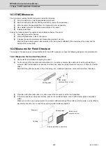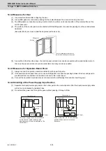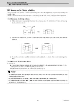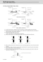
MDS-E/EH Series Instruction Manual
15 Appx. 6: Higher Harmonic Suppression Measure Guidelines
513
IB-1501229-F
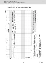
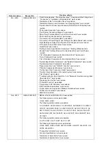
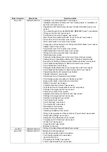
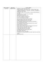
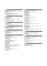
(3) Higher harmonic current flow calculation form
A higher harmonic current flow calculation form is shown below for reference.
No.
1
2
3
4
5
6
7
8
9
10
11
12
13
14
15
Cur
re
nt upper
limit value (
m
A)
Orde
r
(Higher ha
rmonic current flow
upper
limit
per contracted kW x contracted electricity)
Higher harmonic current flow up
p
e
r limit value
Necessity of measures
Total
In all other cases, separate meas
ures must be tak
e
n
If there is a facility that lowers the
higher
ha
rmonics in the factory, o
r when supp
ression
measures are im
plemented, proc
eed to Calculation Form
(Part 2
)
If the current
flow
> current flow u
pper limit value at each order
, the
n
6-pulse equivalent capacity total
Po
Step 2
If P, > 50kVA (6k
V
incoming powe
r), 300kVA
(22, 3
3
kV incoming power),
2000kVA (66kV
or higher incomin
g power), proceed to Step 2. (St
e
p 2 does not nee
d to be complete
d in
all other cases.)
If the device's circuit type cl
assification No. is 10, complete the application shown in
<Format 3>.
Refer to t
he refe
rence and indicate the
circuit type classification No.
, etc.
Indicate the detai
ls of the higher h
a
rmonic generati
ng device.
Step 1
<Instruc
tio
n
s f
o
r com
p
leti
ng f
o
rm
>
5th-
order
(%
)
Device's
maxim
u
m
operat
ion
rate
[a x Pi] (mA
)
Rated curren
t
value for
inco
min
g
po
wer vol
tage
conversi
on
[Ki x Pi]
(kVA)
6-pul
s
e
calcula
tion
coefficien
t
Ki
Circuit
type cl
as-
sificati
on
No.
Pi (kVA)
Total
capacity
Qty. of
devices
(kVA)
Rated
capacity
Type
Maker
Device n
ame
Higher harm
oni
c
genera
tin
g
device
Step
1
:
Det
ails of
hi
gher harm
o
n
ic
ge
nerati
ng device
Inco
min
g
po
wer
volta
g
e
Con
tracte
d
electricit
y
kV
kW
Higher
harm
oni
c curren
t flo
w
p
er order
Step 2
: Calc
u
lat
ion o
f hi
gher
ha
rmoni
c
curre
nt f
low ra
te
Date of accept
anc
e
Applic
atio
n N
o
.
Date o
f a
p
plica
tion
<Form 1>
Indu
stry
User
name
Higher harmonic generating de
vice's hig
h
er harmonic current flow c
a
lculation f
o
rm (Part 1)
6-pul
se
equival
e
nt
capacity
7th-
order
11th-
order
13th-
order
17th-
order
19th-
order
23rd-
order
25th-
order
5th-
order
7th-
order
11th-
order
13th-
order
17th-
order
19th-
order
23rd-
order
25th-
order
Summary of Contents for MDS-E
Page 1: ......
Page 3: ......
Page 15: ......
Page 17: ......
Page 19: ......
Page 21: ......
Page 31: ......
Page 32: ...1 IB 1501229 F 1 Installation ...
Page 76: ...45 IB 1501229 F 2 Wiring and Connection ...
Page 132: ...101 IB 1501229 F 3 Safety Function ...
Page 142: ...111 IB 1501229 F 4 Setup ...
Page 277: ...MDS E EH Series Instruction Manual 4 Setup 246 IB 1501229 F ...
Page 278: ...247 IB 1501229 F 5 Servo Adjustment ...
Page 351: ...MDS E EH Series Instruction Manual 5 Servo Adjustment 320 IB 1501229 F ...
Page 352: ...321 IB 1501229 F 6 Spindle Adjustment ...
Page 404: ...373 IB 1501229 F 7 Troubleshooting ...
Page 455: ...MDS E EH Series Instruction Manual 7 Troubleshooting 424 IB 1501229 F ...
Page 456: ...425 IB 1501229 F 8 Maintenance ...
Page 475: ...MDS E EH Series Instruction Manual 8 Maintenance 444 IB 1501229 F ...
Page 476: ...445 IB 1501229 F 9 Power Backup System ...
Page 494: ...463 IB 1501229 F 10 Appx 1 Cable and Connector Assembly ...
Page 504: ...473 IB 1501229 F 11 Appx 2 D A Output Specifications for Drive Unit ...
Page 514: ...483 IB 1501229 F 12 Appx 3 Protection Function ...
Page 523: ...MDS E EH Series Instruction Manual 12 Appx 3 Protection Function 492 IB 1501229 F ...
Page 524: ...493 IB 1501229 F 13 Appx 4 Compliance to EC Directives ...
Page 528: ...497 IB 1501229 F 14 Appx 5 EMC Installation Guidelines ...
Page 540: ...509 IB 1501229 F 15 Appx 6 Higher Harmonic Suppression Measure Guidelines ...
Page 550: ......
Page 554: ......

