MDS-E/EH Series Instruction Manual
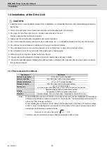
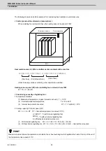
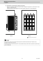
1 Installation
24
IB-1501229-F
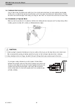
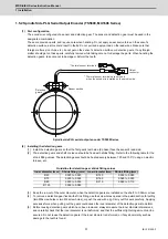
Connection method to a screwless terminal block for fan motor
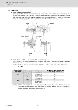
(1) Lead-out length
Strip the sheath of the cable in the range of 8 to 9mm with an appropriate tool.
Applicable cable size: 0.08mm
2
to 2.5mm
2
(28AWG to 12AWG)
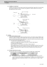
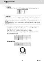
(2) Tool
Use a flat-blade screwdriver whose blade edge size is 0.6×3.5mm for connecting.
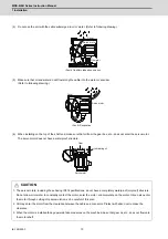
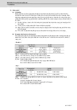
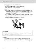
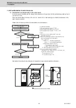
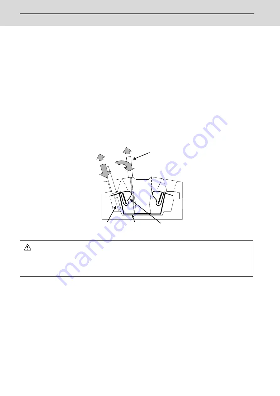
(3) Work procedure
(a) Insert the edge of screwdriver into the insertion point (small square hole) in a diagonal direction. When the
spring touches the blade edge, push the screwdriver down to the position that hits a conductive plate, tilting it
in the inside direction of terminal block. In this state, the spring is completely opened and the screwdriver is
held to the terminal block. Make sure that the screwdriver is completely held, not to create difficulties in
inserting the cable for the next procedure.
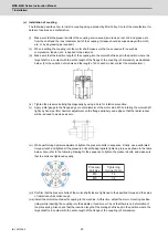
(b) Check the stripped length of cable (8 to 9mm) and insert the cable end slowly along the outside of the insertion
point (big square hole) as far as it will go, not to unravel wires. Make sure not to push thin cables too much.
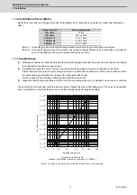
(c) Release the screwdriver while holding one hand against the inserted cable. The spring will be closed and the
cable will be connected.
(d) Gently pull the cable to make sure the connection. No need for a strong pull.
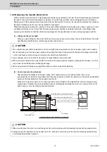
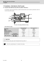
1.2.10 Cable
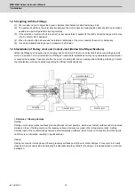
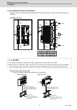
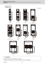
[1] Do not apply the bending stress and the stress from the cable's own weight on the cable connection part.
[2] Make sure that the cable sheathes will not be cut by sharp cutting chips, worn or stepped on by workers or vehicles.
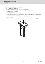
[3] Provide a cable trap because the liquid such as oil or water may enter the motor from the connector by running
along the cable.
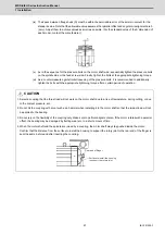
CAUTION
1. Connection of a cable is restricted to one to one spring.
2. For connecting a cable, both twisted wire and solid wire can be used as it is without termination after the sheath has
been stripped. The cable attached with bar terminal can also be connected.
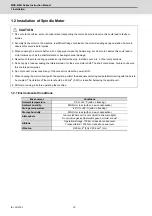
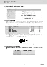
[1]
[2]
[4]
[3]
Screwdriver
Spring
Conductive plate
Wire
Summary of Contents for MDS-E
Page 1: ......
Page 3: ......
Page 15: ......
Page 17: ......
Page 19: ......
Page 21: ......
Page 31: ......
Page 32: ...1 IB 1501229 F 1 Installation ...
Page 76: ...45 IB 1501229 F 2 Wiring and Connection ...
Page 132: ...101 IB 1501229 F 3 Safety Function ...
Page 142: ...111 IB 1501229 F 4 Setup ...
Page 277: ...MDS E EH Series Instruction Manual 4 Setup 246 IB 1501229 F ...
Page 278: ...247 IB 1501229 F 5 Servo Adjustment ...
Page 351: ...MDS E EH Series Instruction Manual 5 Servo Adjustment 320 IB 1501229 F ...
Page 352: ...321 IB 1501229 F 6 Spindle Adjustment ...
Page 404: ...373 IB 1501229 F 7 Troubleshooting ...
Page 455: ...MDS E EH Series Instruction Manual 7 Troubleshooting 424 IB 1501229 F ...
Page 456: ...425 IB 1501229 F 8 Maintenance ...
Page 475: ...MDS E EH Series Instruction Manual 8 Maintenance 444 IB 1501229 F ...
Page 476: ...445 IB 1501229 F 9 Power Backup System ...
Page 494: ...463 IB 1501229 F 10 Appx 1 Cable and Connector Assembly ...
Page 504: ...473 IB 1501229 F 11 Appx 2 D A Output Specifications for Drive Unit ...
Page 514: ...483 IB 1501229 F 12 Appx 3 Protection Function ...
Page 523: ...MDS E EH Series Instruction Manual 12 Appx 3 Protection Function 492 IB 1501229 F ...
Page 524: ...493 IB 1501229 F 13 Appx 4 Compliance to EC Directives ...
Page 528: ...497 IB 1501229 F 14 Appx 5 EMC Installation Guidelines ...
Page 540: ...509 IB 1501229 F 15 Appx 6 Higher Harmonic Suppression Measure Guidelines ...
Page 550: ......
Page 554: ......


