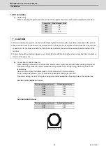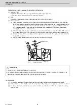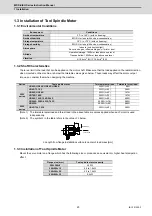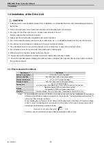
MDS-E/EH Series Instruction Manual
1 Installation
33
IB-1501229-F
1.4.6 Heat Radiation Countermeasures
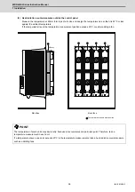
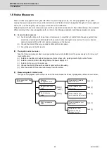
(1) Heat radiation countermeasures in the control panel
In order to secure reliability and life, design the temperature in the panel so that the ambient temperature of each
unit is 55°C or less.
If the heat accumulates at the top of the unit, etc., install a fan or heat exchanger so that the temperature in the
panel remains constant.
Please refer to following method for heat radiation countermeasures.
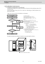
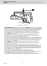
Examples of mounting heat exchanger and temperature measurement positions (reference)
<Point>
[1] Refer to the section “ Heating Value” for the heat
generated by each unit.
[2] Refer to the following calculation for calculation W1 of the
panel’s cooling capacity (thin steel plate).
W1 = U x A x
T
U: 6W/m
2
x °C (with internal agitating fan)
4W/m
2
x °C (without internal agitating fan)
A: Effective heat radiation area [m
2
]
㧔
Heat dissipation area in panel
㧕
Sections contacting other objects are excluded.
T: Internal temperature rise value (10°C)
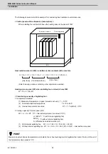
[3] Points in manufacturing and evaluation
Understanding the temperature rise in the panel, and
install a fan or heat exchanger.
T (average value) 10°C
T
max
(maximum value) 15°C
<Hypothetical conditions >
[1] Average temperature in panel: T 55°C
[2] Panel peripheral temperature: Ta 0 to 45°C
[3] Internal temperature rise value: T=T-Ta
max
=10°C
Calculate total heat radiation of each
unit in panel (W)
Manufacturing and evaluation
W
҇
W1
W>W1
T > 10
͠
T 10
͠
Completion
Evaluate temperature
in panel
Comparison of
W and W1
Calculate panel’s cooling capacity
(W1)
Consider heat
exchanger
Consider adding fan or
heat exchanger
Temperature measurement positions
Hea
t
exc
h
a
n
g
e
r
Heat
exchanger
Unit
Relay, etc
Unit
Flow of air
Flow of air
Relay, etc
Summary of Contents for MDS-E
Page 1: ......
Page 3: ......
Page 15: ......
Page 17: ......
Page 19: ......
Page 21: ......
Page 31: ......
Page 32: ...1 IB 1501229 F 1 Installation ...
Page 76: ...45 IB 1501229 F 2 Wiring and Connection ...
Page 132: ...101 IB 1501229 F 3 Safety Function ...
Page 142: ...111 IB 1501229 F 4 Setup ...
Page 277: ...MDS E EH Series Instruction Manual 4 Setup 246 IB 1501229 F ...
Page 278: ...247 IB 1501229 F 5 Servo Adjustment ...
Page 351: ...MDS E EH Series Instruction Manual 5 Servo Adjustment 320 IB 1501229 F ...
Page 352: ...321 IB 1501229 F 6 Spindle Adjustment ...
Page 404: ...373 IB 1501229 F 7 Troubleshooting ...
Page 455: ...MDS E EH Series Instruction Manual 7 Troubleshooting 424 IB 1501229 F ...
Page 456: ...425 IB 1501229 F 8 Maintenance ...
Page 475: ...MDS E EH Series Instruction Manual 8 Maintenance 444 IB 1501229 F ...
Page 476: ...445 IB 1501229 F 9 Power Backup System ...
Page 494: ...463 IB 1501229 F 10 Appx 1 Cable and Connector Assembly ...
Page 504: ...473 IB 1501229 F 11 Appx 2 D A Output Specifications for Drive Unit ...
Page 514: ...483 IB 1501229 F 12 Appx 3 Protection Function ...
Page 523: ...MDS E EH Series Instruction Manual 12 Appx 3 Protection Function 492 IB 1501229 F ...
Page 524: ...493 IB 1501229 F 13 Appx 4 Compliance to EC Directives ...
Page 528: ...497 IB 1501229 F 14 Appx 5 EMC Installation Guidelines ...
Page 540: ...509 IB 1501229 F 15 Appx 6 Higher Harmonic Suppression Measure Guidelines ...
Page 550: ......
Page 554: ......

