background image

MDS-E/EH Series Instruction Manual
1 Installation

35

IB-1501229-F

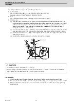
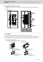
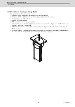
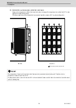
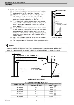
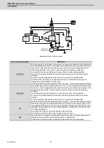
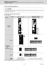
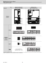
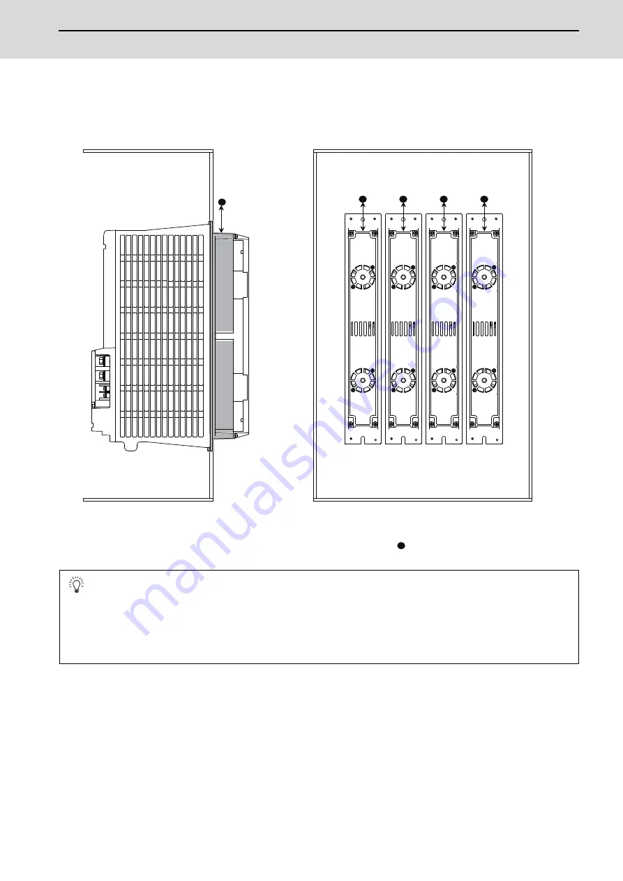
(2) Heat radiation countermeasures outside the control panel

Measure the temperature at 40mm form tops of all units, and design the temperature rise so that it is 20°C or less 
against the ambient temperature.
If the temperature rise at the temperature measurement position exceeds 20°C, consider adding a fan.

 POINT

The temperature of some units may rise locally, because air accumulates at a particular point. Therefore, take a 
temperature measurement in each unit. 
If a temperature at even one point exceeds 20°C in the temperature measurements, take a heat radiation countermeasure 
such as addicting fans. 

40mm


40mm


Temperature measurement position 

Side face 

Back face 


Summary of Contents for MDS-E

Page 1: ......

Page 2: ...n this manual are applicable refer to the specifications for each CNC Notes on Reading This Manual 1 Since the description of this specification manual deals with NC in general for the specifications of individual machine tools refer to the manuals issued by the respective machine tool builders The restrictions and available functions described in the manuals issued by the machine tool builders ha...

Page 3: ......

Page 4: ...e ranked as WARNING and CAUTION Note that some items described as CAUTION may lead to major results depending on the situation In any case important information that must be observed is described DANGER When there is a potential risk of fatal or serious injuries if handling is mistaken WARNING When a dangerous situation or fatal or serious injuries may occur if handling is mistaken CAUTION When a ...

Page 5: ...ve unit Power supply unit Scale interface unit Magnetic pole detection unit Mitsubishi CNC is designed and manufactured solely for applications to machine tools to be used for industrial purposes Do not use this product in any applications other than those specified above especially those which are substantially influential on the public interest or which are expected to have significant influence...

Page 6: ... 15 minutes after turning the power OFF confirm that the CHARGE lamp has gone out and check the voltage between P and N terminals with a tester etc before starting wiring maintenance or inspections Failure to observe this could lead to electric shocks Ground the unit and motor For the motor ground it via the drive unit Wiring maintenance and inspection work must be done by a qualified technician W...

Page 7: ...terial as iron is placed take safety measure not to pinch fingers or hands due to the magnetic attraction force Remove metal items such as watch piercing jewelry necklace etc Do not place portable items that could malfunction or fail due to the influence of the magnetic force When the rotor is not securely fixed to the machine or device do not leave it unattended but store it in the package proper...

Page 8: ...p ignite or rupture if submerged in water or if the poles are incorrectly wired Cut off the main circuit power with the contactor when an alarm or emergency stop occurs 2 Injury prevention Do not apply a voltage other than that specified in this manual on each terminal Failure to observe this item could lead to ruptures or damage etc Do not mistake the terminal connections Failure to observe this ...

Page 9: ...nsporting the units Do not hold the front cover when transporting the unit The unit could drop Always observe the installation directions of the units or motors Secure the specified distance between the units and control panel or between the servo drive unit and other devices Do not install or run a unit or motor that is damaged or missing parts Do not block the intake or exhaust ports of the moto...

Page 10: ... in IPM SPM spindle motor do not heat the rotor higher than 130 C The magnet could be demagnetized and the specifications characteristics will not be ensured Always use a nonmagnetic tool explosion proof beryllium copper alloy safety tool NGK Insulators etc when installing the built in IPM SPM spindle motor direct drive motor and linear servo motor Always provide a mechanical stopper on the end of...

Page 11: ...tion so that signals are not output and emergency stop and other safety circuits are inoperable Do not connect disconnect the cables connected between the units while the power is ON Securely tighten the cable connector fixing screw or fixing mechanism An insecure fixing could cause the cable to fall off while the power is ON When using a shielded cable instructed in the instruction manual always ...

Page 12: ...belt etc or the magnetic brake s failure Install a stop device to ensure safety on the machine side After changing the programs parameters or after maintenance and inspection always test the operation before starting actual operation Do not enter the movable range of the machine during automatic operation Never place body parts near or touch the spindle during rotation Follow the power supply spec...

Page 13: ... with the general drive unit 7 Disposal Take the batteries and backlights for LCD etc off from the controller drive unit and motor and dispose of them as general industrial wastes Do not disassemble the unit or motor Dispose of the battery according to local laws Always return the secondary side magnet side of the linear servo motor to the Service Center or Service Station When incinerating optica...

Page 14: ...ric parts etc and sold to scrap contractors Mitsubishi recommends sorting the product and selling the members to appropriate contractors 2 Requirements for Law for Treatment of Waste and Cleaning a Mitsubishi recommends recycling and selling the product when no longer needed according to item 1 above The user should make an effort to reduce waste in this manner b When disposing a product that cann...

Page 15: ......

Page 16: ... should be disposed of separately from your household waste If a chemical symbol is printed beneath the symbol shown above this chemical symbol means that the battery or accumulator contains a heavy metal at a certain concentration This will be indicated as follows Hg mercury 0 0005 Cd cadmium 0 002 Pb lead 0 004 In the European Union there are separate collection systems for used batteries and ac...

Page 17: ......

Page 18: ...Link CC Link LT and CC Link IE are either trademarks or registered trademarks of Mitsubishi Electric Corporation in Japan and or other countries Other company and product names that appear in this manual are trademarks or registered trademarks of the respective companies ...

Page 19: ......

Page 20: ...andling of our product English This is a class A product In a domestic environment this product may cause radio interference in which case the user may be required to take adequate measures 본 제품의 취급에 대해서 한국어 Korean 이 기기는 업무용 A 급 전자파적합기기로서 판매자 또는 사용자는 이 점을 주의하시기 바라며 가정외의 지역에 서 사용하는 것을 목적으로 합니다 ...

Page 21: ......

Page 22: ...ings Panel Cut Drawings 30 1 4 5 Heating Value 32 1 4 6 Heat Radiation Countermeasures 33 1 5 Installation of the Machine End Encoder 36 1 5 1 Spindle Side ABZ Pulse Output Encoder OSE 1024 Series 36 1 5 2 Spindle Side PLG Serial Output Encoder TS5690 MU1606 Series 37 1 6 Noise Measures 43 2 Wiring and Connection 45 2 1 Part System Connection Diagram 47 2 2 Main Circuit Terminal Block Control Circ...

Page 23: ...n Loop Gain 255 5 2 4 OMR FF Function 258 5 3 Characteristics Improvement 264 5 3 1 Optimal Adjustment of Cycle Time 264 5 3 2 Vibration Suppression Measures 267 5 3 3 Improving the Cutting Surface Precision 274 5 3 4 Improvement of Characteristics during Acceleration Deceleration 277 5 3 5 Improvement of Protrusion at Quadrant Changeover 281 5 3 6 Improvement of Overshooting 285 5 3 7 Improvement...

Page 24: ...ve Unit 439 8 3 2 Replacing the Unit Fan 440 8 3 3 Replacing the Battery 442 9 Power Backup System 445 9 1 Deceleration and Stop Function at Power Failure 446 9 1 1 Specifications of Stop Method for Deceleration and Stop Function at Power Failure System 446 9 1 2 Wiring of Deceleration and Stop Function at Power Failure 447 9 1 3 Setup of Deceleration and Stop Function at Power Failure 448 9 2 Ret...

Page 25: ...ures 499 14 4 Measures for Panel Structure 499 14 4 1 Measures for Control Panel Unit 499 14 4 2 Measures for Door 500 14 4 3 Measures for Operation Board Panel 500 14 4 4 Shielding of the Power Supply Input Section 500 14 5 Measures for Various Cables 501 14 5 1 Measures for Wiring in Panel 501 14 5 2 Measures for Shield Treatment 501 14 5 3 Servo Spindle Motor Power Cable 502 14 5 4 Servo Spindl...

Page 26: ...Control Loop Gain Changeover 3 2 12 Spindle Output Stabilizing Control 3 2 13 High response Spindle Acceleration Decelera tion Function 3 3 Compensation Control Function 3 3 1 Jitter Compensation 3 3 2 Notch Filter 3 3 3 Adaptive Tracking type Notch Filter 3 3 4 Overshooting Compensation 3 3 5 Machine End Compensation Control 3 3 6 Lost Motion Compensation Type 2 3 3 7 Lost Motion Compensation Typ...

Page 27: ... 4 Branch circuit Protection for Control Power Supply 6 4 1 Circuit Protector 6 4 2 Fuse Protection 6 5 Noise Filter 6 6 Surge Absorber 6 7 Relay 6 8 Selection of Link Connection 6 8 1 Connection of L11 and L21 Link 6 8 2 Connection of L and L Link 7 Selection 7 1 Selection of the Servo Motor 7 1 1 Outline 7 1 2 Selection of Servo Motor Capacity 7 1 3 Motor Shaft Conversion Load Torque 7 1 4 Expre...

Page 28: ...converter 1 Base control functions 1 14 Power regeneration control 1 15 Resistor regeneration control 4 Protection function 4 5 Fan stop detection 4 6 Open phase detection 4 7 Contactor weld detection 4 10 Deceleration and stop function at power failure Note 1 4 11 Retraction function at power failure Note 2 5 Sequence function 5 1 Contactor control function 5 3 External emergency stop function 5 ...

Page 29: ...Dual feedback control 2 9 HAS control 2 10 OMR FF control 3 Compensation control function 3 1 Jitter compensation 3 2 Notch filter Variable frequency 4 Fixed frequency 1 Variable frequency 4 Fixed frequency 1 Variable frequency 4 Fixed frequency 1 Variable frequency 4 Fixed frequency 1 Variable frequency 4 Fixed frequency 1 3 3 Adaptive tracking type notch filter 3 4 Overshooting compensation 3 5 ...

Page 30: ...edback control 2 10 OMR FF control 2 11 Control loop gain changeover 2 12 Spindle output stabilizing control 2 13 High response spindle acceleration deceleration function 3 Compensation control function 3 1 Jitter compensation 3 2 Notch filter Variable frequency 4 Fixed frequency 1 Variable frequency 4 Fixed frequency 1 Variable frequency 4 Fixed frequency 1 Variable frequency 4 Fixed frequency 1 ...

Page 31: ......

Page 32: ...1 IB 1501229 F 1 Installation ...

Page 33: ...er touch the rotary sections of the motor during operations Install a cover etc on the shaft 5 Do not apply a load exceeding the tolerable load onto the servo motor shaft The shaft could break Failure to observe this could lead to injuries 6 Do not connect or disconnect any of the connectors while the power is ON Environment Conditions Ambient temperature 0 C to 40 C with no freezing Ambient humid...

Page 34: ... or less HG54 104 154 224 123 223 142 HG204 354 303 453 703 302 24 5m s2 2 5G or less 29 4m s2 3G or less HG903 9 8m s2 1G or less 9 8m s2 1G or less 400V series HG H75 105 24 5m s2 2 5G or less 24 5m s2 2 5G or less HG H54 104 154 HG H204 354 453 703 24 5m s2 2 5G or less 29 4m s2 3G or less HG H903 HQ H903 1103 9 8m s2 1G or less 9 8m s2 1G or less HG H1502 24 5m s2 2 5G or less 24 5m s2 2 5G or...

Page 35: ...on of the encoder installed on the servo motor cannot be changed 1 1 4 Installation Direction 1 There are no restrictions on the installation direction Installation in any direction is possible but as a standard the motor is installed so that the motor power line and encoder cable cannon plugs lead in wires face downward Installation in the standard direction is effective against dripping Measure ...

Page 36: ...N 400V series HG H75T 105T Taper shaft 245N L 33 147N HG H75S 105S Straight shaft 245N L 33 147N HG H54T 104T 154T Taper shaft 392N L 58 490N HG H54S 104S 154S Straight shaft 980N L 55 490N HG H204S 354S 453S 703S Straight shaft 2058N L 79 980N HG H903S Straight shaft 2450N L 85 980N HG H1502S Straight shaft 3234N L 140 1470N HQ H903S Straight shaft 2500N L 52 7 1100N HQ H1103S Straight shaft 2700...

Page 37: ...is as below Excluding special products Accuracy Measurement point Flange size mm Less than 100 SQ 100 SQ 130 SQ 176 SQ 250 SQ 280 SQ or over Run out of the flange surface to the output shaft a 0 05mm 0 06mm 0 08mm 0 08mm Run out of the flange surface s fitting outer diameter b 0 04mm 0 04mm 0 06mm 0 08mm Run out of the output shaft end c 0 02mm 0 02mm 0 03mm 0 03mm a c b ...

Page 38: ...the core doesn t have to be high however it is undesirable for servo In order to fully utilize the servo s efficiency to ensure the maximum durability of the equipments it is required to use a highly rigid coupling and to fully align the shaft cores in the initial installation It is also required to select the optimum flexible coupling according to the working conditions and use it correctly accor...

Page 39: ...racy and backlash amount greatly affect on the machine s positioning accuracy and noise during operation Thus according to the machine s specification appropriately select the accuracy and backlash amount In gear connection it is required to take measures against oil to enter the motor 1 1 8 Oil Water Standards 1 The motor protective format uses the IP type which complies with IEC Standard However...

Page 40: ... horizontally set the connector to face downward When installing vertically or on an inclination provide a cable trap because the liquid such as oil or water may enter the motor from the connector by running along the cable Series Servo motor Oil level mm 200V series HG46 56 12 5 HG96 15 HG75 105 15 HG54 104 154 224 123 223 142 22 5 HG204 354 303 453 703 302 30 HG903 34 400V series HG H75 105 15 H...

Page 41: ...ding those having IP67 specifications do not have a completely waterproof oil proof structure Do not allow oil or water to constantly contact the motor enter the motor or accumulate on the motor Oil can also enter the motor through cutting chip accumulation so be careful of this also 2 Oil may enter the motor from the clearance between the cable and connector Protect with silicon not to make the c...

Page 42: ...o motor moves make sure that the cable bending part is within the range of the optional encoder cable Fix the encoder cable and power cable enclosed with the servo motor 3 Make sure that the cable sheathes will not be cut by sharp cutting chips worn or stepped on by workers or vehicles The bending life of the encoder cable is as shown below Regard this with a slight allowance If the servo motor sp...

Page 43: ...tolerable load onto the servo motor shaft The shaft could break Failure to observe this could lead to injuries 6 Do not connect or disconnect any of the connectors while the power is ON 7 When coupling the motor directly with the spindle perform the adequate centering and parallel correcting with the axis to be coupled The vibration of the motor should be 4 9m s2 0 5G or less after balancing the s...

Page 44: ...he vibration on the points as illustrated below on the brackets where the bearings are stored Make sure to place the motor on a cushioning mat to avoid vibration to the spindle from external sources during measurement Reaction torque is generated when accelerating decelerating the motor so securely fix the motor with a belt etc to avoid rolling during measurement CAUTION 1 We consider key less sha...

Page 45: ...ustment so that the vibration acceleration generated is always 0 5G 4 9m s2 or less The vibration acceleration of 0 5G is about 4 7μm when expressed in terms of the amplitude at the rotation speed of 10 000r min The higher the rotation speed is the smaller the corresponding amplitude becomes YES YES NO NO ӌ0 5G 4 9m s ӌ0 5G 4 9m s 2 2 Confirm the vibration in the motor rotation speed range Disting...

Page 46: ... 5 120 01 SJ DG5 5 120 04T 1470N SJ D7 5 100 01 SJ D7 5 120 01 SJ D11 100 01 SJ DJ11 100 01 SJ DJ15 80 01 SJ V11 01T SJ DG7 5 120 05T SJ DG11 100 03T SJ DG11 120 03T SJ DG15 120 02T K SJ DN7 5 80 01 1960N SJ V22 06ZT 2450N SJ V15 09ZT SJ V18 5 01ZT SJ V18 5 04ZT SJ V22 01ZT SJ V22 04ZT SJ V26 01ZT SJ V11 09T SJ V15 03T SJ V18 5 03T SJ V22 05T 2940N SJ D15 80 01 SJ D18 5 80 01 SJ DN11 80 01 3430N S...

Page 47: ...indle motor to a spindle The incorrect selection of fittings or inadequate installation accuracy can generate abnormal vibration or noise at the coupling It can also shorten the motor or bearing life and can damage them fretting or flaking Contact the manufacturer with any questions regarding the fittings mentioned above Reference Bearing damage Fretting Fretting occurs when contact surfaces produ...

Page 48: ... below show the recommended models manufactured by Deublin and Rix The target models are designed to have these rotary joints attached to the shaft rear end Contact the manufacturer for details of rotary joint Deublin Note 1 Housing both for straight and angle is also available Note 2 Air service with dry running is not available during rotation Note 3 Air service with dry running is also availabl...

Page 49: ...g are the recommended diameters of the pressured area of the coolant joint installed at the end of the motor shaft Note Effective when the coolant pressure is 6 8MPa or less Contact the manufacturer if it exceeds 6 8MPa Note Without a coolant joint the thrust load is applied to the motor side by coolant pressure An excessive thrust load on the spindle motor may lead to abnormal noise or vibration ...

Page 50: ...ment Tolerable value of axial movement Absorbs elongation of the spindle and motor shaft due to thermal expansion These tolerable values are the standard values for which the coupling does not break They are not the standard values for which the load is not applied to the spindle or the motor bearing Thus in order to rotate up to high speed with low vibration and low noise the spindle and the moto...

Page 51: ...evention v Apply a dial gauge to the flange edge or outer diameter of the motor side While rotating the motor shaft lightly by hand perform hammer adjustment on the flange periphery and edge so that the radial runout will be reduced to as close as zero vi While performing hammer adjustment tighten the pressure bolts in sequence Finally use a calibrated torque wrench and tighten all the pressure bo...

Page 52: ...ppropriate tightening torque after a certain period of operation CAUTION 1 Select a coupling that the thrust load will not work on the motor shaft due to a rise of temperature during cutting or due to the coolant pressure etc 2 Do not hit the coupling with a tool such as a hammer when installing it to the motor shaft so that the impact load will not be applied to the bearing 3 Do not rely on the f...

Page 53: ...d more than 90 contact your Mitsubishi Electric dealer To yield good cooling performance provide a space of at least 30mm between the cooling fan and wall If the motor is covered by a structure and the air is not exchanged its cooling performance degrades and the motor is unable to fully exercise its performance which may cause the spindle motor overheat alarm Do not use the spindle motor in an en...

Page 54: ...when using a connector smaller than the wiring hole on the terminal box SJ V SJ VL SJ PMF SJ 4 V Series SJ D DJ DL DG DN Series Screw size Proper torque N m M4 2 0 M5 2 5 M6 3 0 M8 10 0 CAUTION 1 When connecting the power line to the terminal block tighten the screws with proper torque described in this section 2 Make sure to connect the terminal to the terminal block If running the motor with the...

Page 55: ...d length of cable 8 to 9mm and insert the cable end slowly along the outside of the insertion point big square hole as far as it will go not to unravel wires Make sure not to push thin cables too much c Release the screwdriver while holding one hand against the inserted cable The spring will be closed and the cable will be connected d Gently pull the cable to make sure the connection No need for a...

Page 56: ... or produces an equivalent or higher heat dissipation effect Environment Conditions Ambient temperature 0 C to 40 C with no freezing Ambient humidity 80 RH or less with no dew condensation Storage temperature 15 C to 70 C with no freezing Storage humidity 90 RH or less with no dew condensation Atmosphere Indoors no direct sunlight No corrosive gas inflammable gas oil mist or dust Altitude Operatio...

Page 57: ...he designated environment conditions 5 Do not let conductive objects such as screws or metal chips etc or combustible materials such as oil enter the units 6 Do not block the units intake and outtake ports Doing so could lead to failure 7 The units and servo motor are precision devices so do not drop them or apply strong impacts to them 8 Do not install or run units or servo motor that is damaged ...

Page 58: ...ing the panel If required install a fan in the panel to agitate the heat in the upper portion of the units 60mm 67mm 75mm 92mm A Exhaust Inlet Filter 100mm or more 1mm or more 60mm 260 mm 100mm or more 10mm or more 10mm or more 80mm or more 100mm or more 100mm or more 60mm or more 60mm or more 60mm Exhaust 75mm or more 80mm or more 114mm or more Radiation fin size Installation clearance A Filter a...

Page 59: ... exhaust size more than the area that is a total of the cooling fan area 60mm width unit 90mm width unit 120mm width unit 150mm width unit 150mm width unit 240mm width unit 300mm width unit 150mm width unit 150mm width unit 150mm width unit E CV 450 E EH CV E SP 320 E V1 320W E SP 240 EH V1 160W EH SP 160 105 30 170 60 105 170 75 105 45 105 170 105 75 75 132 75 105 170 75 200 69 25 101 5 190 85 13...

Page 60: ...ecurely install door packing 5 If there is a rear cover always apply packing 6 Oil will tend to accumulate on the top Take special measures such as oil proofing to the top so that oil does not enter the cabinet from the screw holds 7 After installing each unit avoid machining in the periphery If cutting chips etc stick onto the electronic parts trouble may occur 8 When using the unit in an area wi...

Page 61: ... hole to match the unit width Unit mm POINT Attach packing around the square hole to provide a seal 342 360 10 8 342 360 82 10 342 360 142 60 10 10 342 360 112 52 8 8 8 Unit width 60mm 2 M5 screw hole Unit width 90mm 2 M5 screw hole Unit width 150mm 4 M5 screw hole Unit width 120mm 2 M5 screw hole Square hole Square hole Square hole Square hole ...

Page 62: ...l 1 Installation 31 IB 1501229 F Unit mm POINT Attach packing around the square hole to provide a seal 341 360 222 120 9 10 341 360 282 180 10 9 Unit width 240mm 4 M5 screw hole Unit width 300mm 4 M5 screw hole Square hole Square hole ...

Page 63: ...272 V1 320 59 307 V3 20 60 71 SP 240 100 520 CV 370 53 343 V1 320W 72 399 V3 40 102 123 SP 320 118 688 CV 450 104 392 V3 80 139 111 SP 400 148 897 CV 550 164 431 SP 640 196 1231 Servo drive unit Spindle drive unit Power supply unit Power backup unit Type MDS EH Heating value W Type MDS EH Heating value W Type MDS EH Heating value W Type MDS EH Heating value W Type MDS DH Heating value W Inside pan...

Page 64: ...ate W1 U x A x T U 6W m 2 x C with internal agitating fan 4W m 2 x C without internal agitating fan A Effective heat radiation area m 2 㧔Heat dissipation area in panel㧕 Sections contacting other objects are excluded T Internal temperature rise value 10 C 3 Points in manufacturing and evaluation Understanding the temperature rise in the panel and install a fan or heat exchanger T average value 10 C...

Page 65: ...ature in panel around each unit T 55 C 2 External peripheral temperature Ta 0 to 45 C 3 Internal temperature rise value DT T Ta MAX 10 C 2 Cooling capacity of control panel W1 W1 U A DT DT Internal temperature rise value 10 C U 6W m2 C with internal agitating fan 4W m2 C without internal agitating fan A Effective heat radiation area m2 1 With internal agitating fan W1 6 1 26 10 75 6 W 60 W 2 Witho...

Page 66: ...perature If the temperature rise at the temperature measurement position exceeds 20 C consider adding a fan POINT The temperature of some units may rise locally because air accumulates at a particular point Therefore take a temperature measurement in each unit If a temperature at even one point exceeds 20 C in the temperature measurements take a heat radiation countermeasure such as addicting fans...

Page 67: ...ended coupling Recommendation 1 Recommendation 2 Manufacturer Tokushu Seiko Eagle Model Model M1 FCS38A Resonance frequency 1374Hz 3515Hz Position detection error 0 8 10 3 1 2 10 3 Tolerable speed 20 000r min 10 000r min Mis alignment Core deviation 0 7mm 0 16mm Angle displacement 1 5 1 5 Outline dimensions Max length 74 5mm 33mm Max diameter Φ57mm Φ38mm CAUTION Confirm that the gear ratio pulley ...

Page 68: ... The detection gears should be heated evenly between 120 and 150 C using an electric furnace etc Guideline for detection gear shrink fitting values 3 Keep the run out of the outer diameter when the detection gears are installed on the shaft to 0 02mm or less 4 To remove a detection gear fixed with shrink fitting use the screw holes opened in the axial direction for pulling two M5 screw holes or tw...

Page 69: ... diameter section 5 Make sure that force is not constantly applied on the sensor s lead wires 6 Check the gap between the encoder sensor and the gear 0 3 0 05mm Shape of notched fitting section Installing dimension of the sensor section POINT To install the sensor section the notched fitting section on the machine side must have the specified dimensions The sensor s installation accuracy is assure...

Page 70: ...n accuracy Whether the gap between the sensor section and the gear is ensured correctly or not can be confirmed using the servo diagnosis screen PLG diagn on NC while rotating the spindle motor in an open loop control Confirm it according to the following procedures 1 Set the spindle parameter 13018 bit1 SP018 bit1 to 1 to enable an open loop control 2 Turn the NC and drive unit power OFF and disc...

Page 71: ...spindle PLG diagnosis For details of each diagnosis signal bit refer to the next page When an error is detected with spindle PLG diagnosis 1 is displayed on the corresponding diagnosis signal bit 1 Power ON Open loop control enabled 2 Power ON again 5 Open loop control disabled 6 Power OFF 1 Power ON 2 Power ON again 6 Power OFF 4 Judgment with the diagnosis signal bit by the PLG diagnosis display...

Page 72: ...ation between the sensor and the center of the gear 4 B phase amplitude excessive The B phase amplitude is larger than the specified value Too small gap 5 B phase amplitude too small The B phase amplitude is smaller than the specified value Excessive gap 6 B phase offset excessive The B phase offset is larger than the specified value to side The deviation between the sensor and the center of the g...

Page 73: ...n 2 bit 1 oplp Open loop control This allows the operation in which no encoder feedback signals are used It is used when adjusting the encoder etc 0 Disable 1 Enable 13113 SP113 OPLP Current command value for open loop Set the current command value for when the open loop control is enabled When 0 is set the state will be the same as when 50 is set When not using set to 0 The open loop control is e...

Page 74: ...d the shield of the servo encoder s cable with a cable clamp c Accurately ground the AC reactor 2 Propagation noise measures Take the following measures when noise generating devices are installed and the power supply unit or drive unit could malfunction a Install a surge killer on devices magnetic contacts relays etc which generate high levels of noise b Install a power line filter in the stage b...

Page 75: ...ise could be propagated to the signal wire and cause malfunction because of the magnetic induction noise or static induction noise In this case take the following measures a Install devices easily affected as far away from the drive unit as possible b Lay devices easily affected as far away from the signal wire of the drive unit as possible c Avoid laying the signal wire and power line in a parall...

Page 76: ...45 IB 1501229 F 2 Wiring and Connection ...

Page 77: ... The excessive length could generate noise 5 Do not mistake the direction of the diodes for the surge absorption installed on the DC relay for the motor brake and contactor magnetic contactor control The signal might not be output when a failure occurs 6 Electronic devices used near the drive units may receive magnetic obstruction Reduce the effect of magnetic obstacles by installing a noise filte...

Page 78: ...the ground of the motor to the ground of the connected drive unit MC2 OPTH1 2 T S R CN1A CN4 CN9 L1 L2 L3 L11 TE3 TE1 CN9 CN1B L CN2 TE1 PLG CN4 TE3 TE2 L L L11 L21 TE2 L21 CN3 CN1A CN4 CN9 CN1B MU MV MW CN2L CN2M LU LV LW TE1 TE3 TE2 L L L11 L21 CN3L CN3M MC MC1 EMG1 EMG2 PE PE PE PE CN24 CN41 MDS E EH MDS E EH MDS E EH CN23 CN8 CN5 CN8 CN20 CN5 L LU LV LW Optical communication cable 24VDC ۑ Cont...

Page 79: ...r control terminal LU LV LW Motor output Single axis unit Servo spindle motor power output terminal The servo spindle motor power terminal U V W is connected LU LV LW MU MV MW Motor output Dual axis unit Servo spindle motor power output terminal L axis M axis The servo spindle motor power terminal U V W is connected LU LV LW MU MV MW SU SV SW Motor output Triple axis unit Servo motor power output ...

Page 80: ...his item could lead to rupture or damage etc Unit Terminal MDS E CV 37 to 75 MDS E CV 110 to 185 MDS EH CV 37 to 185 Terminal position Terminal specification Pin assignment 1 TE1 2 TE2 3 TE3 4 Screw size M4 12 Tightening torque 1 2Nm The PE screw size is the same as TE1 2 3 4 1 2 3 4 1 L3 L2 L1 Note This is a bottom view 2 0Nm M5 x 12 L1 L2 L3 Compatible unit Screw size Tightening torque All of CV...

Page 81: ... 3 4 1 2 1 2 3 4 6 0Nm M8 x 16 L1 L2 L3 Compatible unit Screw size Tightening torque All of CV 11 0Nm M10 x 20 L1 L2 L3 M8 x 16 6 0Nm Compatible unit Screw size Tightening torque 550 to 750 E CV EH CV 550 4 0Nm M6 x 18 L L 4 0Nm M6 x 16 Compatible unit Screw size Tightening torque 300 to 450 E CV EH CV 300 to 450 550 to 750 550 1 2Nm M4 x 10 L11 L21 Compatible unit Screw size Tightening torque 300...

Page 82: ...nt 1 TE1 2 TE2 3 TE3 4 2 3 1 4 2 3 1 4 LW LV LU Note This is a bottom view For L axis Note This is a bottom view 2 0Nm M5 x 12 M8 x 16 6 0Nm LU LV LW Compatible unit Screw size Tightening torque 240 to 320 EH V1 EH SP 320W E V1 E SP 320 160 to 200 160 to 160W 100 to 160 4 0Nm M6 x 18 L L Compatible unit Screw size Tightening torque All of V1 SP 1 2Nm M4 x 10 L11 L21 Compatible unit Screw size Tigh...

Page 83: ...ower supply unit and connect with DC connection bar 1 3 2 4 LU LV LW 6 0Nm M8 x 15 M10 x 20 11 0Nm Screw size Tightening torque Compatible unit 600 400 to 640 EH V1 EH SP E SP 200 200 to 480 Note Refer to POINT below 4 0Nm M6 x 16 L L Compatible unit Screw size Tightening torque 400 to 640 200 200 to 600 EH V1 EH SP E SP 1 2Nm M4 x 10 L11 L21 Compatible unit Screw size Tightening torque 400 to 640...

Page 84: ... 1 4 2 3 1 4 LW LV LU MW MV MU Note This is a bottom view For L axis For M axis 2 0Nm M5 x 12 LU LV LW MW MV MU Screw size Tightening torque Note This is a bottom view E SP2 EH V2 E V2 4 0Nm M6 x 18 L L 20 to 16080 10 to 160 20 to 160W Compatible unit Screw size Tightening torque 1 2Nm M4 x 10 E SP2 EH V2 E V2 L11 L21 20 to 16080 10 to 160 20 to 160W Compatible unit Screw size Tightening torque E ...

Page 85: ...tion Terminal specification Pin assignment 1 TE1 Note This is bottom view Note This is bottom view 2 TE2 3 TE3 4 Screw size M4 12 Tightening torque 1 2Nm 4 2 3 1 4 2 3 1 LW LV LU MW MV MU SW SV SU For L axis For M axis For S axis LW LV LU MW MV MU SW SV SU For L axis For M axis For S axis 4 0Nm M6 x 18 L L Compatible unit Screw size Tightening torque All of V3 M4 x 10 1 2Nm L11 L21 Compatible unit...

Page 86: ...hown as an example Unit Terminal MDS E V1 MDS EH V1 160W or less MDS EH V1 200 Connector position Connector specification 1 CN1A 2 CN1B Optical communication connector 3 CN5 4 CN9 5 CN4 6 CN8 7 CN2L 8 CN3L 9 CN20 5 9 1 4 7 2 8 3 6 9 5 4 1 2 7 8 3 6 No 1 No 5 No 10 No 1 No 11 No 20 Pin No No 8 No 2 No 1 No 7 No 9 No 1 No 10 No 2 No 3A No 2A Pin No No 1A No 3B No 2B No 1B ...

Page 87: ...shown as an example Unit Terminal MDS E EH V2 Connector position Connector specification 1 CN1A 2 CN1B Optical communication connector 3 CN5 4 CN9 5 CN4 6 CN8 7 CN2L 8 CN3L 9 CN2M 10 CN3M 11 CN20 5 11 1 4 7 2 8 9 10 3 6 No 1 No 5 No 10 No 1 No 11 No 20 Pin No No 8 No 2 No 1 No 7 No 9 No 1 No 10 No 2 No 3A No 2A Pin No No 1A No 3B No 2B No 1B ...

Page 88: ... example Unit Terminal MDS E EH V3 Connector position Connector specification 1 CN1A 2 CN1B Optical communication connector 3 CN5 4 CN9 5 CN4 6 CN8 7 CN2L 8 CN3L 9 CN2M 10 CN3M 11 CN2S 12 CN3S 13 CN20 1 4 7 2 8 6 5 13 3 9 10 11 12 No 1 No 5 No 10 No 1 No 11 No 20 Pin No No 8 No 2 No 1 No 7 No 9 No 1 No 10 No 2 No 3A No 2A Pin No No 1A No 3B No 2B No 1B ...

Page 89: ...s an example Unit Terminal MDS E SP 320 or less MDS EH SP 160 or less MDS E SP 400 or more MDS EH SP 200 or more Connector position Connector specification 1 CN1A 2 CN1B Optical communication connector 3 CN5 4 CN9 5 CN4 6 CN8 7 CN2L 8 CN3L 5 1 4 7 2 8 3 6 5 4 1 2 7 8 3 6 No 1 No 5 No 10 No 1 No 11 No 20 Pin No No 8 No 2 No 1 No 7 No 9 No 1 No 10 No 2 ...

Page 90: ... are shown as an example Unit Terminal MDS E SP2 80 or less MDS E SP2 16080 Connector position Connector specification 1 CN1A 2 CN1B Optical communication connector 3 CN5 4 CN9 5 CN4 6 CN8 7 CN2L 8 CN3L 9 CN2M 10 CN3M 1 4 7 2 8 9 10 6 5 3 1 4 7 2 8 9 10 6 5 3 No 1 No 5 No 10 No 1 No 11 No 20 Pin No No 8 No 2 No 1 No 7 No 9 No 1 No 10 No 2 ...

Page 91: ... with an anti misinsertion mechanism and can be connected only to the power supply output of each certain axis The connector without the anti misinsertion mechanism CNU01SEF AWG14 can be connected to the power supply output of all axes Axis name Connector model name Applicable cable Strip length mm Connection lever Manufacturer Size Insulator outer dimension For CV CNU01SECV AWG14 AWG16 to 8 7 8mm...

Page 92: ...e connection lever as shown in the following illustration and push it down to open the spring Keep the connection lever pushed down and insert the stripped wire to the insert hole Confirm the insert depth so that the wire insulator is not caught Release the connection lever to fix the wire Pulling the wire for confirming the secure connection Core Sheath Strip length Unraveling or bending of core ...

Page 93: ...ext stage s drive unit CN4 Connector for communication between power supply unit master side and drive unit Connection when using one power supply unit CAUTION 1 Connect the NC and the drive units by the optical communication cables The distance between the NC and the final drive unit must be within 30m and the specified bending radius for wiring inside panel 25mm and for wiring outside panel 50mm...

Page 94: ... supply unit Connections when using two power supply units within a single NC communication bus system CAUTION 1 The drive unit receiving power L L from each power supply unit must always have NC communication bus connection at the NC side of each power supply unit 2 If two or more power supply units are connected in the drive system confirm that the units are not connected with each other through...

Page 95: ...supplying power L L from MDS EM EMH unit install the optical communication cables in a manner that makes MDS EM EMH unit the final axis Failure to observe this could lead to damage unit 3 When installing the additional axis unit install the spindle drive unit with maximum capacity adjacent to the MDS EM EMH SPV3 and connections for other drive units should be such that the total TE2 wiring length ...

Page 96: ...ement of 1500mm or more multiple power supply units are required 5 Arrange large capacity drive units at the left of the power supply unit with the clearance between the drive units being 1mm POINT 1 Arrange large capacity drive units at the left of the power supply unit with the clearance between the drive units being 1mm 2 Power supply units equivalent to the number of large capacity drive units...

Page 97: ... 6 9 10 1 2 3 1 RQ 2 RQ 3 4 BAT 5 LG GND 6 SD 7 SD 8 P5 5V 9 10 SHD CNT Encoder connector Brake connector These are 24VDC and have no polarity Optional cable CNV2E Optional cable Refer to Appx 1 for details on the cable treatment Max Motor brake magnetic wiring Refer to section Wiring of the motor magnetic brake for details Encoder connector Pin No No 10 No 2 No 9 No 1 Power connector Pin Pin Name...

Page 98: ...LG RQ SD 2 4 6 8 10 P5 5V RQ SD BT 1 3 5 7 9 TE1 3 LW 2 LV 1 LU LU LV LW 1 2 3 Name Name Pin Pin Name Pin Ground Name Pin Name Pin Name Pin Pin No Encoder connector CN2L Power connector Optional cable CNV2E Refer to Appx 1 for details on the cable treatment Max 30m Power wire and grounding wire Refer to Specification manual for details on selecting the wire Brake connector These are 24VDC and have...

Page 99: ... P5 5V RQ SD BT 1 3 5 7 9 TE1 3 LW 2 LV 1 LU LU LV LW 1 2 3 Name Name Pin Pin Name Pin Ground Name Pin Name Pin Name Pin Pin No Encoder connector CN2L Power connector Optional cable CNV2E Refer to Appx 1 for details on the cable treatment Max 30m Power wire and grounding wire Refer to Specification manual for details on selecting the wire Brake connector These are 24VDC and have no polarity Refer ...

Page 100: ... B1 B2 1 2 CMV1 R10P 8 4 5 7 6 9 10 1 2 3 1 RQ 2 RQ 3 4 BAT 5 LG GND 6 SD 7 SD 8 P5 5V 9 10 SHD MDS E EH V1 CNT Name Pin Name Pin Name Ground Pin Max 30m Name Pin Pin Name Pin No Encoder connector CN2L Power connector Optional cable CNV2E Refer to Appx 1 for details on the cable treatment Power wire and grounding wire Refer to Specification manual for details on selecting the wire Brake connector ...

Page 101: ...ake unit is required for HG H1502 Refer to section Dynamic brake unit wiring for details LG RQ SD 2 4 6 8 10 P5 5V RQ SD BT 1 3 5 7 9 CN2L CMV1 R10P 8 4 5 7 6 9 10 1 2 3 1 RQ 2 RQ 3 4 BAT 5 LG GND 6 SD 7 SD 8 P5 5V 9 10 SHD U V W BU BW BV 8 9 2 6 8 9 2 6 MDS EH V1 200 LU LV LW CNT U V W M8 screw OHS1 OHS2 M4 screw BU BV BW M4 screw Max 30m Pin Name Optional cable CNV2E Refer to Appx 1 for details ...

Page 102: ...including when SIN wave signal output is converted to Mitsubishi serial signal output with a scale manufacturer encoder interface unit can directly connect to the drive unit CN3L CN2L MDS E EH V1 1 3 5 7 9 2 4 6 8 10 P5 5V RQ SD BT LG RQ SD Pin No Encoder connector CN3L Name Name Pin CNV2E cable Max 30m CNV2E cable Max 30m Encoder type setting SV025 62xx Servomotor Ball screw side encoder Pin No 1...

Page 103: ...encoder interface unit MDS EX HR The distance coded reference scale interface is also available CN3L CN2L MDS E EH V1 1 3 5 7 9 P5 5V A Z B 2 4 6 8 10 LG A B Z ABZSEL Cable prepared by user Max 30m Linear scale Rectangular wave signal output Encoder type setting SV025 82xx CNV2E cable Max 30m Pin No Encoder connector CN3L Name Name Pin Pin Servomotor No 10 No 2 No 9 No 1 CN3L CN2L MDS E EH V1 1 3 ...

Page 104: ...2 Connecting Mitsubishi serial signal output linear scale when using MDS E EH V2 The FB signal of the linear scale is divided to each axis control inside the 2 axis drive unit An external option unit is not required MDS E EH V2 CN2M CN2L CN3L MDS EX HR 11 Cable prepared by user Linear scale SIN wave signal output Encoder type setting Primary axis SV025 A2xx Secondary axis SV025 D2xx CNV2E cable Ma...

Page 105: ...of the linear scale is divided to each drive unit with the signal division unit MDS B SD MDS E EH V1 MDS E EH V1 MDS B SD Encoder division unit CN2L CN3L CN2L CN3L Cable prepared by user Linear scale SIN wave signal output Encoder type setting SV025 A2xx CNV2E cable Max 30m Primary axis Secondary axis CNV2E D cable Max 30m Encoder type setting SV025 D2xx Primary axis Secondary axis ...

Page 106: ...n the fan rotates reversely reconnect BU and BW reversely and then check the blowoff direction BW BW BV BV BU BU W V U U V W CN2L BU BW BV MDS E EH SP LG RQ MT2 SD 2 4 6 8 10 P5 5V RQ MT1 SD 1 3 5 7 9 LU LV LW Name Pin Name Pin Max 30m Spindle motor Power cable Option cable CNP2E 1 Example for 3 phase cooling fan power supply Note Either a single phase or 3 phase power supply is used for the cooli...

Page 107: ...le side PLG serial output encoder TS5690 CN2L CN3L MDS E EH SP LG A B Z ABZSEL 2 4 6 8 10 A B Z 1 3 5 7 9 P5 5V Spindle side encoder Spindle motor Pin No Name Pin Name Pin CNP2E 1 cable max 30m CNP3EZ cable max 30m Encoder connector CN3L Spindle No 10 No 2 No 9 No 1 CN2L CN3L MDS E EH SP LG RQ SD 2 4 6 8 10 RQ SD 1 3 5 7 9 P5 5V Spindle motor Pin No Name Pin Name Pin CNP2E 1 cable max 30m CNP2E 1 ...

Page 108: ...manual for details on selecting the wire Ground Optional cable CNV2E Refer to Appx 1 for details on the cable treatment Max 30m Encoder connector Name Pin Name Pin Name Pin Pin No Encoder connector CN2L No 9 No 1 No 10 No 2 Name Pin CMV1 R10P 8 4 5 7 6 9 10 1 2 3 A B C D U V W A B C D CE05 2A18 10PD MDS E SP LG RQ SD 2 4 6 8 10 P5 5V RQ SD BT 1 3 5 7 9 CN2L LU LV LW 1 RQ 2 RQ 3 CNT 4 BAT 5 LG GND ...

Page 109: ...Name Pin Name Pin Pin No Encoder connector CN2 Power wire and grounding wire Refer to Specification manual for details on selecting the wire No 9 No 1 No 10 No 2 A B C D CE05 2A22 22PD U V W A B C D CMV1 R10P 8 4 5 7 6 9 10 1 2 3 1 RQ 2 RQ 3 CNT 4 BAT 5 LG GND 6 SD 7 SD 8 9 10 SHD P5 5V MDS E SP LG RQ SD 2 4 6 8 10 P5 5V RQ SD BT 1 3 5 7 9 CN2L LU LV LW Power connector Ground Optional cable CNV2E ...

Page 110: ...eatment Max 30m Encoder connector Name Pin Name Pin Name Pin Name Pin Pin No Encoder connector CN2L Power wire and grounding wire Refer to Specification manual for details on selecting the wire No 9 No 1 No 10 No 2 CMV1 R10P 8 4 5 7 6 9 10 1 2 3 A B C D U V W A B C D MS3102A14S 2P MDS E EH SP LG RQ SD 2 4 6 8 10 P5 5V RQ SD BT 1 3 5 7 9 CN2L LU LV LW 1 RQ 2 RQ 3 CNT 4 BAT 5 LG GND 6 SD 7 SD 8 9 10...

Page 111: ...nit s magnetic contact drive circuit and a surge absorber is installed to protect the element Therefore a leakage current of approx 15mA is passed Confirm that the exciting coil in the magnetic contact will not function at 15mA or less CAUTION 1 The power supply unit is equipped with a power supply regenerative type converter an AC reactor is surely installed in the power supply line 2 When connec...

Page 112: ...capacity and connect the CN4 of the drive unit which is used as a final axis when a spindle drive unit is included spindle drive unit with that of the power supply unit 4 Confirm that the power supply units are not connected with each other through the TE2 L L wiring before turning the power ON MC2 T S R CN1A CN4 L1 L2 L3 L11 TE3 TE1 CN1B L L CN4 TE3 TE2 L L L11 L21 TE2 L21 CN1A CN1B TE3 TE2 L L L...

Page 113: ...k etc FG Grounding to stabilize the operation of the devices etc Suppress noise 2 Grounding cable size Earth wire size should follow the following table POINT Do not connect the grounding cable from each unit directly to the grounding plate Noise from other units could result in malfunctions Type Grounding cable size Required grounding MDS E EH CV Unit Larger than thickness of wire connected to TE...

Page 114: ...tion below an external power supply circuit is controlled by the CN20 connector output Dynamic brake unit is controlled simultaneously for the servo drive unit with the capacity of MDS E V1 320W or larger and MDS EH V1 160W or larger Refer to Dynamic brake unit wiring for details CAUTION 1 CN20 connector and the brake can be connected directly because the servo drive unit contains the surge absorb...

Page 115: ...control to fix the position with the motor brake by the servo OFF command during the motor stop for PLC axis use 1 axis drive unit During emergency stop the servo OFF is applied to all axes at same time so a brake control is not affected CAUTION When using SBC Safe Brake Control function the CN9 connector is dedicated to the M axis and the motor brakes cannot be connected in parallel Refer to 3 3 ...

Page 116: ...uence 0 Normal 1 High speed 1 When SV017 is set to bit2 0 2 When SV017 is set to bit2 1 1500 1000 500 0 ON OFF ON OFF Emergency stop EMG Dynamic brake Motor brake control output CN9B Servo ready signal RDY Servo ready completion signal SA Motor brake control sequences when an emergency stop is canceled 1 Ready completion Command input enable Time ms ON Cancel Cancel ON Cancel ON 1500 1000 500 0 ON...

Page 117: ...od POINT Using the high speed ready ON sequence set the parameter for all the axes including the spindle Especially when it is not set for the power supply control axis power supply will not work at high speed sequence CAUTION When SV017 bit2 1 SP017 bit2 1 is set for the model using an external dynamic brake the Ready completion will be delayed by 10ms to ensure the external contactor operation t...

Page 118: ...unit Do not use for applications other than emergencies normal braking etc The internal resistor could heat up and lead to fires or faults POINT When you use a servo motor with a brake please wire between 3A pin and 3B pin of CN20 connector 1A P24 2A DBR 3A MBR1 3B MBR2 1B 24G V W U 14 13 b a C SK R 0 5 V W 2 1 3 U U V W a b NC a b 13 14 5 6 2 1 3 4 M MDS D DBU CN20 3B MBR2 3A MBR1 2B N C 2A DBR 1...

Page 119: ...ngs For a switch or relay to be wired use a switch or relay that satisfies the input output voltage current conditions Connector Input condition Connector Output condition CN9 Switch ON 18VDC to 25 2VDC 4 3mA or more CN9 Output voltage 24VDC 5 Switch OFF 4VDC or less 2mA or less Tolerable output current 50mA or less CN24 Switch ON 18VDC to 25 2VDC 4 3mA or more Switch OFF 4VDC or less 2mA or less ...

Page 120: ...mal operation could occur 2 1 1 20 4 1k 4A 1A 24V 4 1k 8 10 18 MPO1 MPO2 DICOM 24G 24V D01 D02 24V 13 DI1 16 D03 MPO3 4 1k 2 DI2 4 1k 3 DI3 4 1k 14 DI4 4 1k 17 DI5 D04 12 D05 MPO4 MPO5 7 2 CN24 connector CN9 connector CN9 connector Servo spindle drive unit Switch Power supply unit Input circuit Output circuit Servo spindle drive unit Relay etc The part indicated by the must be prepared by the user...

Page 121: ...relay control MPO4 CN9 7 Reservation MPO5 CN9 12 Reservation Device name Connector pin No Signal name Signal changeover parameter Spindle input signal MPI1 CN9 13 Reservation Orientation function Proximity switch signal SP227 bitF C 4 MPI2 CN9 2 Reservation MPI3 CN9 3 Reservation MPI4 CN9 14 Reservation MPI5 CN9 17 Reservation Spindle input signal MPO1 CN9 8 Coil changeover signal L axis MPO2 CN9 ...

Page 122: ...xes The signal output turns ON when the all axes satisfy the conditions theoretical product output Specified speed signal output sequence 0 mm min 0 mm min OFF ON ON 㻌 㻌 OFF ON ON 0 mm min 0 mm min 0 mm min 0 mm min 㻌 OFF ON ON 0 mm min 0 mm min 0 mm min 0 mm min 0 mm min 0 mm min Speed command Specified speed mm min Output signal Machine end speed For 1 axis drive unit MDS E EH V1 MDS E EH SP As ...

Page 123: ... However when SV033 bitD 1 the setting range is from 0 to 32767 100mm min 2282 SV082 SSF5 Servo function 5 bit 9 8 dos2 Digital signal output 2 selection 00 Disable 01 Specified speed output Spindle drive unit 13018 PR SP018 SPEC2 Spindle specification 2 bit 8 spsu Command speed limit value 0 33 750 r min 1 135 000 r min 13030 SP030 SDT2 2nd speed detection setting value Set the specified speed of...

Page 124: ...ith SP029 is applied on the speed when changing from the low speed coil to the high speed coil and the high speed coil to the low speed coil Spindle motor coil changeover control 13028 SP028 SDTS Speed detection set value Set the motor speed for detecting the speed If the motor speed drops below the set speed the speed detection signal turns ON The standard setting is 10 of the maximum motor speed...

Page 125: ...contactor s OFF ON time The standard setting is 150 Setting range 0 to 3500 ms 2 Current limit after coil changeover Following a coil changeover the current is limited SP116 for the period specified by the current limit timer SP115 in order to stabilize control Because position loop control synchronous tap C axis control etc that occurs immediately after a coil changeover will result in unstable c...

Page 126: ...a changeover circuit Coil changeover circuit Wiring of motor coil connection MC1 ON MC2 OFF connection MC1 OFF MC2 ON POINT Wire it according to each 6 terminal s sign U V W X Y Z of spindle motor for the coil changeover U V W Y Z U V W MC2 MC1 X Spindle motor MC1 Contactor to connect low speed coil connection MC2 Contactor to connect high speed coil Δ connection Spindle drive unit Motor terminal ...

Page 127: ...indle motor for the coil changeover U1 V1 W1 U2 V2 W2 U V W MC1 MC2 Spindle motor Spindle drive unit MC1 Contactor to connect low speed coil 1st connection MC2 Contactor to connect high speed coil 2nd connection Motor terminal U2 U1 V1 W1 V2 W2 W U V Spindle drive unit The terminal which is assembled at the contactor ON U2 U1 V1 W1 V2 W2 W U V The terminal which is assembled at the contactor ON Sp...

Page 128: ...Set the spindle parameter to the pulley ratio for belt drive or to the gear ratio for gear drive 20 DICOM 13 DI1 MDS E EH SP 4 1k CN9 DICOM MDS E EH SP 4 1k CN9 DICOM MDS E EH SP 4 1k CN9 24G 20 13 DI1 20 13 DI1 24VDC Current direction Proximity switch Shield Case ground Detection circuit 24VDC Current direction Proximity switch Shield Case ground Detection circuit Select the polarity of DICOM Con...

Page 129: ...entation 0 Interpolation mode Use the interpolation mode gain SP002 1 Non interpolation mode Use the non interpolation mode gain SP001 bit D Interpolation mode selection 1 zero point return initiated during rotation 0 Non interpolation mode 1 Interpolation mode bit C Z phase detection method 0 Follows Z phase detection direction bit0 1 Rotates in the commanded direction at Z phase detection speed ...

Page 130: ...Position shift amount for orientation The orientation stop position can be moved with this parameter setting although normally the position is Z phase position During multi point orientation control the stop position is determined by the total value of this parameter and the position data for multi point orientation of PLC input Setting range 35999 to 35999 0 01 3109 zdetspd Z phase detection spee...

Page 131: ...request ORC When ORC is changed from 0 to 1 the Z phase passed will be 0 control output2 bit0 Control output 5 bitD Zero point re detection complete ORF If the zero point re detection is completed after the zero point re detection request control input5 bitD is set to1 ORF 1 is set If the zero point re detection request is set to 0 ORF 0 is set ...

Page 132: ...101 IB 1501229 F 3 Safety Function ...

Page 133: ...o enhance the reliability of the brake start In this function the brake start signal is output redundantly and it enhances the reliability of signal path to the brake start and also diagnosis the brake signal output end It detects the brake start circuit defect and wiring defect etc WARNING Precautions for the safety function described in this manual are as follows Read carefully all the following...

Page 134: ...ustment for the safety related parts in the system has been completed 5 When replacing the drive unit make sure that the new product is the same as the one before the replacement After the installation be sure to confirm the performance of the safety function before operating the system 6 Perform all the risk assessments and safety level certifications for the whole device and system The use of a ...

Page 135: ...on 1 System configuration and wiring STO function shuts off the motor power of all axes or the designated axis in the system Warning A4 sub number 0001 is detected while STO function is shutting off the motor power A system configuration example when using network STO function CAUTION This function is set with the NC Refer to the smart safety observation function for details of the setup and contr...

Page 136: ...ff by using this connector with external safety device The following wiring and parameter setting SV113 SP229 bit8 are required when using the connector CN8 Dedicated wiring STO function can be disabled by inserting the following connector to CN8 Manufacturer Tyco Electronics Type Connector set MR D05UDL3M B Connector for dedicated wiring STO signal CN8 and signal array Signal name Connector pin N...

Page 137: ...rectly to the drive unit safety is ensured by inputting synonymous STO signals redundantly to shut off the energy supply with the independent control 2 Diagnosis for the input status of STO signal can be performed by using TOF signal SERVO ON SERVO OFF STO signal switching timing STO1 signal STO2 signal Servo OFF signal Actual door operation Input the STO signal in servo OFF status Drive unit dete...

Page 138: ...r less 5 Input resistance 4kΩ 6 Tolerable chattering time 1ms or less 7 Input signal holding time 600ms or more 8 Input circuit operation delay time 10ms typ 30ms or less 1 Insulation method Insulation 2 Rated load voltage 24V 3 Rated current 40mA or less 4 Maximum current 50mA or less 5 Rush current 100mA or less 6 Internal voltage drop 1 3V or less CAUTION Maximum 1 3V of voltage drop occurs ins...

Page 139: ...shutoff function of STO function performed by the H W When using network STO function only make sure to set to 0 Servo parameter 2313 SV113 SSF8 Servo function 8 bit 8 sto Dedicated wiring STO function 0 Dedicated wiring STO function unused 1 Dedicated wiring STO function used Spindle parameter 13229 SP229 SFNC9 Spindle function 9 bit 8 sto Dedicated wiring STO function 0 Dedicated wiring STO func...

Page 140: ...nit and Drive unit occurs the safety communication alarm is issued Additionally when status is inconsistent with the crosscheck in the safe brake control circuit inside the drive unit the V07 DRV safe circuit error SBC circuit diagnosis error alarm is detected Refer to the NC function smart safety observation function for details Safety communication Brake signal Circuit information Safety observa...

Page 141: ... details 2 Motor brake control connector CN9 output circuit When using the brake of M axis As shown in the illustration below the brake control is enabled by using DO output of CN9 for an external power supply circuit CAUTION 1 For SBC the brake control of the CN20 connector is dedicated to the L axis and the brake control of the CN9 connector is dedicated to the M axis 2 The maximum brake tolerab...

Page 142: ...111 IB 1501229 F 4 Setup ...

Page 143: ...it MDS E EH V1 V2 SP MDS E EH V3 SP2 setting Rotary switch setting AXIS NO 0 1st axis 1 2nd axis 2 3rd axis 3 4th axis 4 5th axis 5 6th axis 6 7th axis 7 8th axis 8 9th axis 9 10th axis A 11th axis B 12th axis C 13th axis D 14th axis E 15th axis F 16th axis L axis M axis 1 axis spindle drive unit MDS E EH SP 2 axis spindle drive unit MDS E SP2 1 axis servo drive unit MDS E EH V1 2 axis servo drive...

Page 144: ...setting all the switches OFF Rotary switch setting Setting items 0 Normal setting 1 to 3 Setting prohibited 4 External emergency stop setting 5 to F Setting prohibited CAUTION An axis set unused is not included in the functional safety Power supply unit MDS E EH CV The switches are OFF when facing bottom as illustrated M axis Setting unused axis L axis Setting unused axis S axis Setting unused axi...

Page 145: ...ency stop when starting the servo system 2 Do not insert or extract the external STO input connector CN8 after starting the servo system Motor power will be shut off and it may cause the collision of machine Executing initial communication with NC Drive unit initialization complete Waiting for NC power start up Emergency stop state The LED will alternate between F E7 not lit is the set axis No Rep...

Page 146: ...ontrol 1 Set the standard parameters in the section 4 2 5 List of Standard Parameters for Each Servo Motor 2 4 2 1 Setting of Servo Specification Parameters 3 4 2 2 Setting of Machine Side Encoder 4 4 2 3 Setting of Distance coded Reference Scale For speed command synchronous control 1 Set the standard parameters in the section 4 2 5 List of Standard Parameters for Each Servo Motor 2 4 2 1 Setting...

Page 147: ...sition control These parameters are set automatically by the NC system 0 Incremental 1 Absolute position control 2 Electronic gear related parameters Servo control is performed by changing NC command unit to servo control unit with the following parameters electric gear Even if each parameter is within the setting range overflow of the electric gear coefficient may be occur When the overflow of th...

Page 148: ...h MDS E CV 450 MDS EH CV 450 0045h MDS E CV 550 MDS EH CV 550 0055h MDS EH CV 750 0075h When the emergency stop input signal of the power supply unit is enabled Note Set the power supply rotary switch to 4 Power supply unit is not connected 0000h MDS E CV 37 MDS EH CV 37 0044h MDS E CV 75 MDS EH CV 75 0048h MDS E CV 110 MDS EH CV 110 0051h MDS E CV 185 MDS EH CV 185 0059h MDS E CV 300 MDS EH CV 30...

Page 149: ...ET2AS RNG1 0 For a linear scale Set the number of pulses per ball screw lead in one kp increments For a rotary scale Set the number of pulses per revolution in one kp increments Note that the value must be input in increments of 10K pulses the 1st digit of the setting value is 0 If any restriction is imposed due to the above condition also set SV117 in one pulse increments 2317 PR SV117 RNG1ex Exp...

Page 150: ...0 0125 65536 remainder quotient Other manufacturers Rectangular wave output scale Not required Signal frequency μm 4 82 SV018 1000 signal cycleμm 4 65536 remainder quotient Manufacturer Encoder type Interface unit type Control resolution SV025 SV019 SV117 MAGNESCALE SR75 SR85 Not required 0 1μm A2 SV018 0 1 0 0 05μm A2 SV018 0 05 0 0 01μm A2 SV018 0 01 0 HEIDENHAIN LS187 LS487 EIB192M A4 20μm 20 1...

Page 151: ... 05μm A2 SV018 0 05 0 RCN2590M Not required 268 435 456p rev 62 0 4096 RCN5390M Not required 67 108 864p rev 62 0 1024 RCN5590M Not required 268 435 456p rev 62 0 4096 RCN8390M Not required 536 870 912p rev 62 0 8192 ROC425M Not required 32 000 000p rev 62 32000 0 ROC2390M Not required 67 108 864p rev 62 0 1024 ECA4000 Series Not required 134 217 728p rev 62 0 2048 Mitutoyo AT343 Not required 0 05...

Page 152: ...d polarity 1 Reverse polarity 4 Setting of the machine side encoder alarm detection When using a rectangular wave linear scale set the following parameters The rectangular wave scale determined no signal by the difference from the motor end FB Set no signal 2 special detection width considering a delay of machine end position generated by the torsion of the ball screw 2235 SV035 SSF4 Servo functio...

Page 153: ...e reference marks arranged at regular intervals on the distance coded reference scale When the base reference mark interval SV130 and the reference mark s auxiliary interval are in the specified relationship the distance coded reference scale is judged to be connected Following is the specified relationship SV130 1000 SV131 4 No remainder Setting range 0 to 32767 mm 2331 PR SV131 DPITS Auxiliary r...

Page 154: ...6 When SV137 32767 the distance coded reference check function is disabled 2334 SV134 RRn0 Distance coded reference check revolution counter 2335 SV135 RPn0H Distance coded reference check position within one rotation High 2336 SV136 RPn0L Distance coded reference check position within one rotation Low Set this parameter to operate distance coded reference check when using distance coded reference...

Page 155: ...ontrol with 2 axis drive unit MDS E EH V2 make sure to set L axis as primary axis When performing the speed command synchronous control with 3 axis drive unit MDS E V3 make sure to set L axis as primary axis and M axis as secondary axis 2 The rectangular waveform output scale is not available for the speed command synchronous control 3 The distance coded reference scale is not available for the sp...

Page 156: ...xcessive error detection width during servo ON 6 6 6 SV024 INP In position detection width 50 50 50 SV025 MTYP Motor Encoder type 22BA 22BB 22BC SV026 OD2 Excessive error detection width during servo OFF 6 6 6 SV027 SSF1 Servo function 1 4000 4000 4000 SV028 0 0 0 SV032 TOF Torque offset 0 0 0 SV033 SSF2 Servo function 2 0000 0000 0000 SV034 SSF3 Servo function 3 0000 0000 0000 SV035 SSF4 Servo fu...

Page 157: ...or detection width during servo ON 6 6 6 6 6 6 6 6 SV024 INP In position detection width 50 50 50 50 50 50 50 50 SV025 MTYP Motor Encoder type 2241 2242 2243 2244 224F 2245 2245 2246 2247 2248 SV026 OD2 Excessive error detection width during servo OFF 6 6 6 6 6 6 6 6 SV027 SSF1 Servo function 1 4000 4000 4000 4000 4000 4000 4000 4000 SV028 0 0 0 0 0 0 0 0 SV032 TOF Torque offset 0 0 0 0 0 0 0 0 SV...

Page 158: ...ion width during servo ON 6 6 6 6 6 6 6 6 SV024 INP In position detection width 50 50 50 50 50 50 50 50 SV025 MTYP Motor Encoder type 2264 2266 2268 2249 224A 224B 2265 2267 SV026 OD2 Excessive error detection width during servo OFF 6 6 6 6 6 6 6 6 SV027 SSF1 Servo function 1 4000 4000 4000 4000 4000 4000 4000 4000 SV028 0 0 0 0 0 0 0 0 SV032 TOF Torque offset 0 0 0 0 0 0 0 0 SV033 SSF2 Servo func...

Page 159: ...0 150 150 SV023 OD1 Excessive error detection width during servo ON 6 6 6 6 6 SV024 INP In position detection width 50 50 50 50 50 SV025 MTYP Motor Encoder type 2241 2242 2243 2244 2245 SV026 OD2 Excessive error detection width during servo OFF 6 6 6 6 6 SV027 SSF1 Servo function 1 4000 4000 4000 4000 4000 SV028 0 0 0 0 0 SV032 TOF Torque offset 0 0 0 0 0 SV033 SSF2 Servo function 2 0000 0000 0000...

Page 160: ...ction width during servo ON 6 6 6 6 6 6 SV024 INP In position detection width 50 50 50 50 50 50 SV025 MTYP Motor Encoder type 2247 2248 2249 224A 224B 224D SV026 OD2 Excessive error detection width during servo OFF 6 6 6 6 6 6 SV027 SSF1 Servo function 1 4000 4000 4000 4000 4000 4000 SV028 0 0 0 0 0 0 SV032 TOF Torque offset 0 0 0 0 0 0 SV033 SSF2 Servo function 2 0000 0000 0000 0000 0000 0000 SV0...

Page 161: ...l 150 150 SV023 OD1 Excessive error detection width during servo ON 6 6 SV024 INP In position detection width 50 50 SV025 MTYP Motor Encoder type 2258 2259 SV026 OD2 Excessive error detection width during servo OFF 6 6 SV027 SSF1 Servo function 1 4000 4000 SV028 0 0 SV032 TOF Torque offset 0 0 SV033 SSF2 Servo function 2 0000 0000 SV034 SSF3 Servo function 3 0000 0000 SV035 SSF4 Servo function 4 0...

Page 162: ...he more accurately the command can be followed and the shorter the set tling time in positioning gets however note that a bigger shock will be applied to the machine during accel eration deceleration When using the SHG control also set SV004 PGN2 and SV057 SHGC When using the OMR FF control set the servo rigidity against quadrant projection or cutting load etc For the tracking ability to the comma...

Page 163: ...ral control Standard setting 1364 Standard setting in the SHG control 1900 Adjust the value by increasing decreasing this by about 100 at a time Raise this value to improve contour tracking accuracy in high speed cutting Lower this value when the position droop does not stabilize when the vibration of 10 to 20Hz occurs Setting range 1 to 9999 Set the fixed value of each motor Set the standard valu...

Page 164: ... back lash etc at quadrant change is too large This sets the compensation torque at quadrant change when an axis feed direction is reversed by the proportion to the stall torque Whether to enable the lost motion compensation and the method can be set with other parameters Type 2 When SV027 bit9 8 10 Compatible with obsolete type Set the type 2 method compensation torque The standard setting is dou...

Page 165: ...e parameters are set automatically by the NC system 0 Incremental 1 Absolute position control bit 6 5 Not used Set to 0 bit 4 sdir Sub side encoder feedback Set the machine side encoder s installation polarity 0 Forward polarity 1 Reverse polarity bit 3 vfb Speed feedback filter 0 Stop 1 Start 4500Hz bit 2 seqh Ready on sequence 0 Normal 1 High speed bit 1 dfbx Dual feedback control Control the po...

Page 166: ...hen SV117 0 the setting range is from 0 to 32767 kp When SV117 0 the setting range is from 0 to 65535 p Normally set to 0 For linear motor Set the number of pulses of the encoder per magnetic pole pitch with SV118 For direct drive motor Set the number of pulses per revolution of the motor side encoder For 1000 pulse unit resolution encoder set the number of pulses to SV020 in increments of 1000 pu...

Page 167: ...0 Standard setting value OD1 OD2 Rapid traverse rate mm min 60 PGN1 2 mm Related parameters SV026 Setting range 0 to 32767 mm However when SV084 bitC 1 the setting range is from 0 to 32767 μm Set the in position detection width Set the positioning accuracy required for the machine The lower the setting is the higher the positioning accuracy will be However the cycle time settling time becomes long...

Page 168: ...T2AS OSA676ET2AS pen 6 For serial signal output rotary scale including MDS EX HR pen 6 For rectangular wave signal output linear scale pen 8 For serial signal output linear scale including MDS EX HR and MPI scale pen A For speed command synchronization control Primary axis pen A Secondary axis pen D For linear motor pen A For direct drive motor pen 2 bit B 8 ent HEX 3 Speed encoder For general mot...

Page 169: ...or series HG H75 41h HQ H903 58h HG H105 42h HQ H1103 59h HG H54 43h HG H104 44h HG H154 45h HG H204 47h HG H354 48h HG H453 49h HG H703 4Ah HG H903 4Bh HG H1502 4Dh For linear motor and direct drive motor follow the settings stated in respective materials Set the excessive error detection width during servo OFF When set to 0 the excessive error alarm detection will be ignored so do not set to 0 S...

Page 170: ...ameters SV031 SV042 SV034 bitF C bit 9 8 lmc Lost motion compensation type Set this parameter when the protrusion at quadrant change is too large Type 2 has an obsolete type compatible control bit9 8 00 Compensation stop 01 Setting prohibited 10 Type 2 11 Setting prohibited Set the compensation amount in SV016 LMC1 and SV041 LMC2 Note When SV082 bit1 1 the lost motion compensation type 3 will be s...

Page 171: ... Not used Set to 0 Setting range 18000 to 18000 electrical angle 0 01 Noise at high speed rotation including rapid traverse can be reduced by lowering the speed loop gain at high speeds Set the speed at which the speed loop gain changes Use this with SV006 VGN2 When not using set to 0 Setting range 0 to 9999 r min When 100 is set the voltage reduction amount equivalent to the logical non energizat...

Page 172: ...ngs When 1 is set the compensation will not be performed in the direction of the command Related parameters SV027 bitB A SV034 bitF C SV042 SV082 bit2 Setting range 1 to 100 Stall current Note that the range will be 1 10000 Stall current 0 01 when SV082 bit2 is 1 Set the unbalance torque on vertical axis and inclined axis When the vertical axis pull up function is enabled the pull up compensation ...

Page 173: ...he specified speed signal output speed SV073 0 mm min 1 100mm min Related parameters SV073 bit C 8 Not used Set to 0 bit 7 5 nfd2 Depth of Notch filter 2 Set the depth of Notch filter 2 SV046 bit7 6 5 000 001 18 1 dB 010 12 0 dB 011 8 5 dB 100 6 0 dB 101 4 1 dB 110 2 5 dB 111 1 2 dB bit 4 fhz3 Notch filter 3 0 Stop 1 Start 1125Hz bit 3 1 nfd1 Depth of Notch filter 1 Set the depth of Notch filter 1...

Page 174: ... 4μm E 28 μm F 30μm bit B 8 linN The number of parallel connections when using linear motors for linear Set to 2 to perform 1 amplifier 2 motor control by linear servo bit 7 5 Not used Set to 0 bit 4 dcd linear direct drive motor 0 Normal setting 1 DC excitation mode Related parameters SV061 SV062 SV063 bit 3 Not used Set to 0 bit 2 mohn Thermistor temperature detection linear direct drive motor 0...

Page 175: ...es of that of rapid traverse G0 When set to 0 detection of collision detection method 1 during cutting feed will be ignored G1 Collision detection level G0 collision detection level SV060 clG1 bit B cl2n Collision detection method 2 0 Enable 1 Disable bit A clstp Collision detection method 1 disabled during stop 0 Collision detection method 1 enabled during stop 1 Collision detection method 1 disa...

Page 176: ... MDS EH CV 110 11 MDS E CV 185 MDS EH CV 185 19 MDS E CV 300 MDS EH CV 300 30 MDS E CV 370 MDS EH CV 370 37 MDS E CV 450 MDS EH CV 450 45 MDS E CV 550 MDS EH CV 550 55 MDS EH CV 750 75 When the emergency stop input signal of the power supply unit is enabled Note Set the power supply rotary switch to 4 Power supply unit is not connected 00 MDS E CV 37 MDS EH CV 37 44 MDS E CV 75 MDS EH CV 75 48 MDS...

Page 177: ...IT2 29 Setting prohibited 2A 2C FCUA RB75 2 2 units connected in parallel 2D FCUA RB55 2 units connected in parallel 2E Setting prohibited 2F MR RB1H 4 33 MR RB3M 4 34 MR RB3G 4 35 MR RB5G 4 36 bit 7 4 emgx External emergency stop function Set the external emergency stop function 0 Disable 4 Enable bit 3 0 Not used Set to 0 Set the motor axis conversion total load inertia including motor itself in...

Page 178: ...pending on the command directions Normally set to 0 Setting range 1 to 100 Stall current Note that when SV082 bit2 is 1 the setting range is between 1 and 10000 Stall current 0 01 Set the disturbance observer filter band Normally set to 100 Setting values of 49 or less is equal to 0 setting To use the disturbance observer also set SV037 JL and SV044 OBS2 When disturbance observer related parameter...

Page 179: ...rive unit use the servo axis that controls vertical axis drop prevention control to control the power supply connect with CN4 Related parameters SV033 bitE SV055 SV056 Setting range 0 to 20000 ms When set to 0 and the pull up function is enabled SV033 bitE 1 the alarm S02 2233 Initial param eter error occurs Set the position loop gain during spindle synchronization control synchronous tapping and ...

Page 180: ...cale machine side encoder exceeds the val ue set by this parameter it will be judged as overrun and Alarm 43 will be detected When 1 is set if the differential velocity between the motor side encoder and the machine side encoder exceeds the 30 of the maximum motor speed it will be judged as overrun and Alarm 43 will be detected When 0 is set overrun will be detected with a 2mm width For linear ser...

Page 181: ... Make sure to set the value 6 times that of SV049 When not using the SHG control set to 0 Setting range 0 to 1200 rad s Set the torque estimated gain when using the collision detection function The standard setting value is the same as the load inertia ratio SV037 setting value including motor inertia Set to 0 when not using the collision detection function Related parameters SV032 SV035 bitF 8 SV...

Page 182: ...magnetic pole shift amount measurement value is unsteady adjust the value in increments of 5 Related parameters SV061 SV063 Setting range 32768 to 32767 When the DC excitation is running SV034 bit4 1 0 to 100 Stall current Set output scale of the D A output channel 1 in increment of 1 100 When 0 is set the magnification is the same as when 100 is set When the DC excitation is running SV034 bit4 1 ...

Page 183: ... However when SV033 bitD 1 the setting range is from 0 to 32767 100mm min Only for MDS E EH and MDS EM EMH This parameter is set automatically by the NC system Select the servo functions A function is assigned to each bit Set this in hexadecimal format bit F A Not used Set to 0 bit 9 npg Earth fault detection 0 Disable 1 Enable standard Set 0 and it is constantly Enable for MDS EJ EJH Series bit 8...

Page 184: ...g prohibited bit 9 8 dos2 Digital signal output 2 selection bit9 8 00 Disable 01 Specified speed output 10 Setting prohibited 11 Setting prohibited bit 7 3 Not used Set to 0 bit 2 ccu Lost motion overshoot compensation compensation amount setting increment 0 Stall current 1 Stall current 0 01 bit 1 lmc3 Lost motion compensation type 3 Set this when protrusion at a quadrant change is too big 0 Stop...

Page 185: ...Notch filter 5 Set the depth of Notch filter 5 SV088 bit7 6 5 000 001 18 1 dB 010 12 0 dB 011 8 5 dB 100 6 0 dB 101 4 1 dB 110 2 5 dB 111 1 2 dB bit 4 Not used Set to 0 bit 3 1 nfd4 Depth of Notch filter 4 Set the depth of Notch filter 4 SV087 bit3 2 1 000 001 18 1 dB 010 12 0 dB 011 8 5 dB 100 6 0 dB 101 4 1 dB 110 2 5 dB 111 1 2 dB bit 0 Not used Set to 0 2283 SV083 SSF6 Servo function 6 nfd4 nf...

Page 186: ...ffective current display Set the machine system s spring constant when selecting lost motion compensation type 3 When not using set to 0 Related parameters SV016 SV041 SV082 bit2 1 SV086 Setting range 0 to 32767 0 01 μm Set the machine system s viscous coefficient when selecting lost motion compensation type 3 When not using set to 0 Related parameters SV016 SV041 SV082 bit2 1 SV086 Setting range ...

Page 187: ... motor speed at the position command stop Be aware when setting the parameter as the setting units for general motors and linear motors are different For general motor When the command speed error detection level is set to 0 the magnetic pole position error 3E is detected at 10r min Set 10 as standard This detects the magnetic pole position error 3E when the motor rotation speed is 100r min and mo...

Page 188: ...o 0 when not using OMR FF control Setting range 0 to 300 rad s Not used Set to 0 Set the current feed forward rate in OMR FF control The standard setting is 10000 Setting value of 0 is equal to 10000 100 setting Set to 0 when not using OMR FF control Setting range 0 to 32767 0 01 Select the servo functions A function is assigned to each bit Set this in hexadecimal format bit F 9 Not used Set to 0 ...

Page 189: ...mal format bit F 9 Set to 8 when HG46 56 96 motors are driven by MDS E V3 Set to 0 for other cases bit 8 nohis History of communication error alarm between NC and DRV 34 36 38 39 0 Enable 1 Disable bit 7 cse Command speed monitoring function 0 Disable 1 Enable Normal setting bit 6 0 Not used Set to 0 2314 SV114 SSF9 Servo function 9 cse nohis ...

Page 190: ... 001 Notch filter 1 frequency 010 Notch filter 2 frequency 011 Notch filter 3 frequency always displays 1125Hz 100 Notch filter 4 frequency 101 Notch filter 5 frequency Other settings setting prohibited bit B ade5 Notch filter 5 Adaptive follow up function 0 Disable 1 Enable bit A ade4 Notch filter 4 Adaptive follow up function 0 Disable 1 Enable bit 9 ade2 Notch filter 2 Adaptive follow up functi...

Page 191: ...rsion compensation function When compensating the torsion amount in the reverse direction only set to 0 0 Stop 1 Start For high accuracy binary resolution encoder set the number of pulses to four bite data of SV117 high order and SV019 low order by pulse p When SV117 0 the setting unit of SV019 is kp Refer to SV019 for details Related parameters SV019 SV020 SV118 Setting range 1 to 32767 When usin...

Page 192: ...en using distance coded reference scale During the distance coded reference check initial setup SV137 RAER 1 set the following items on the NC drive monitor screen after the distance coded reference check initial setup warning A3 turns OFF SV134 Rn SV135 Pn SV136 MPOS When reference point is set the warning A3 turns OFF To enable the distance coded reference check function SV081 bit3 1setting and ...

Page 193: ...ts alarm 42 The standard setting value is basic reference mark interval SV130 4 SV137 0 setting carries out the same operation as the standard setting value SV137 1 setting enables the distance coded reference initial set up mode and displays setting values of SV134 to SV136 on NC drive monitor To enable the distance coded reference check function SV081 bit3 1setting and a battery option are need ...

Page 194: ...a workpiece the speed loop gain is switched au tomatically in response to inertia by setting the speed loop gain and workpiece inertia multiplier in advance The speed loop gain SV199 RTGM changes in response to the estimated inertia ratio SV200 RTJX based on the speed loop gain SV005 VGN1 and the inertia multiplier SV037 JL which were adjusted when no workpiece was mounted When SV199 is set to 0 t...

Page 195: ...ard value is 3000 when using HG46 HG56 or HG96 Setting range 0 to 5000 rad s Not used Set to 0 Set the communication interpolation unit among drive units in high speed synchronous tapping control When set to 0 it will be regarded as 20 0 05μm is set Related parameters SV129 Setting range 0 to 2000 1 μm Not used Set to 0 2406 SV206 FCTC Full closed torsion compensation control torsion amount 2407 2...

Page 196: ... so the time depends on the inertia size 1 Setting of the maximum rotation speed Set the maximum rotation speed of S commands synchronous tapping etc 3001 slimt 1 Limit rotation speed Gear 00 Set the spindle rotation speed for maximum motor speed when gear 00 is selected Set the spindle rotation speed for the S analog output 10V during analog spindle control Setting range 0 to 999999 r min 3005 sm...

Page 197: ...turned ON the spindle rotates at the speed of setting value for this parameter until Z phase is detected twice When 3106 bitF 1 Spindle zero point proximity switch detection enabled also proximity switch is detected Note When spindle zero point proximity switch detection is enabled the rotation direction of the orientation zero point return synchronous tapping spindle C axis will follow Z phase de...

Page 198: ...ode selection in orientation Select non interpolation mode when vibration occurs since the gain is high during the orientation 0 Interpolation mode Use the interpolation mode gain SP002 1 Non interpolation mode Use the non interpolation mode gain SP001 2 Setting of the gear ratio Set the following parameters depending on the spindle drive method direct gear drive belt drive for the machine 13057 P...

Page 199: ...019 6000 SP097 0 TS5690 256 teeth SP019 8000 SP097 0 TS5690 384 teeth SP019 12000 SP097 0 ERM280 1200 teeth SP019 4800 SP097 0 ERM280 2048 teeth SP019 8000 SP097 0 MPCI SP019 7200 SP097 0 MBE205 SP019 2000 SP097 0 GEL2449M 524 288 p rev SP019 0 SP097 8 Setting range When SP097 0 the setting range is from 0 to 32767 kp When SP097 0 the setting range is from 0 to 65535 p 13020 PR SP020 RNG2 Main sid...

Page 200: ...nd the machine side encoder exceeds the set value it is judged as an overrun and Alarm 43 is detected When 1 is set if the differential velocity between the motor side encoder and the machine side encoder exceeds the 30 of the maximum motor speed it will be judged as overrun and Alarm 43 will be detected When 0 is set overrun will be detected with 2 In the full closed loop control normally set thi...

Page 201: ...he safety of the surroundings before starting the operation Do not operate at high speed rotation at first After checking that there are no problems as abnormal noise vibration etc from the spindle at start up with no load and small S commands raise the S commands gradually When vibration or abnormal noise occurs during the test operation adjust or set the speed gain or the notch filter For the fi...

Page 202: ...000 1200 1200 1200 1000 1200 1000 SP029 SDTR Speed detection reset width 30 30 30 30 30 30 30 30 SP030 SDT2 2nd speed detection setting value 0 0 0 0 0 0 0 0 SP031 MTYP Motor type 2200 2200 2200 2200 2200 2200 2200 2200 SP032 PTYP Power supply type Regenerative resistor type SP033 SFNC1 Spindle function 1 0000 0000 0000 0000 0000 0000 0000 0000 SP034 SFNC2 Spindle function 2 0000 0000 0000 0000 00...

Page 203: ...que constants H 1938 1961 1961 1934 1907 1947 1947 1942 SP141 Motor unique constants H 86 98 98 83 77 145 145 145 SP142 Motor unique constants H 0 0 0 0 0 0 0 0 SP143 0 0 0 0 0 0 0 0 SP144 Motor unique constants H 0 0 0 0 0 0 0 0 SP145 Motor unique constants H 388 335 467 436 478 369 460 440 SP146 Motor unique constants H 423 428 433 423 422 434 437 435 SP147 Motor unique constants H 71 66 66 73 7...

Page 204: ...generative resistor type SP033 SFNC1 Spindle function 1 0000 0000 0000 0000 SP034 SFNC2 Spindle function 2 0000 0000 0000 0000 SP035 SFNC3 Spindle function 3 1600 1600 1600 1600 SP036 SFNC4 Spindle function 4 0000 0000 0000 0000 SP037 JL Load inertia scale 100 100 100 100 SP038 FHz1 Notch filter frequency 1 0 0 0 0 SP046 FHz2 Notch filter frequency 2 0 0 0 0 SP047 EC Inductive voltage compensation...

Page 205: ...3 1918 1921 2001 SP141 Motor unique constants H 183 148 196 197 155 SP142 Motor unique constants H 0 0 0 0 SP143 0 0 0 0 SP144 Motor unique constants H 0 0 0 0 SP145 Motor unique constants H 321 231 320 260 315 334 SP146 Motor unique constants H 430 312 431 354 433 437 SP147 Motor unique constants H 50 52 47 49 59 SP148 Motor unique constants H 492 365 331 341 332 SP149 Motor unique constants H 82...

Page 206: ...Motor type 2200 2200 SP032 PTYP Power supply type Regenerative resistor type SP033 SFNC1 Spindle function 1 0000 0000 SP034 SFNC2 Spindle function 2 0000 0000 SP035 SFNC3 Spindle function 3 1600 1600 SP036 SFNC4 Spindle function 4 0000 0000 SP037 JL Load inertia scale 100 100 SP038 FHz1 Notch filter frequency 1 0 0 SP046 FHz2 Notch filter frequency 2 0 0 SP047 EC Inductive voltage compensation gai...

Page 207: ... H 3111 2975 SP139 Motor unique constants H 2550 2755 SP140 Motor unique constants H 1934 1907 SP141 Motor unique constants H 83 77 SP142 Motor unique constants H 0 0 SP143 0 0 SP144 Motor unique constants H 0 0 SP145 Motor unique constants H 436 478 SP146 Motor unique constants H 423 422 SP147 Motor unique constants H 73 78 SP148 Motor unique constants H 691 682 SP149 Motor unique constants H 608...

Page 208: ...ed detection setting value 0 0 0 0 0 0 0 0 SP031 MTYP Motor type 2200 2200 2200 2200 2200 2200 2200 2200 SP032 PTYP Power supply type Regenerative resistor type SP033 SFNC1 Spindle function 1 0000 0000 0000 0000 0000 0000 0000 0000 SP034 SFNC2 Spindle function 2 0000 0000 0000 0000 0000 0000 0000 0000 SP035 SFNC3 Spindle function 3 1600 1600 1600 1600 1600 1600 1600 1600 SP036 SFNC4 Spindle functi...

Page 209: ... 3148 3252 4030 3809 SP139 Motor unique constants H 2427 2355 2376 2427 2499 2427 2099 2140 SP140 Motor unique constants H 1947 1956 1953 1947 1942 1947 1873 1976 SP141 Motor unique constants H 87 98 148 148 144 148 198 194 SP142 Motor unique constants H 0 0 0 0 0 0 0 0 SP143 0 0 0 0 0 0 0 0 SP144 Motor unique constants H 0 0 0 0 0 0 0 0 SP145 Motor unique constants H 473 467 463 464 462 462 133 1...

Page 210: ... 1000 1000 1000 1000 1000 1000 SP227 SFNC7 Spindle function 7 0000 0000 0000 0000 0000 0000 0000 0000 SP232 Not used 0000 0000 0000 0000 0000 0000 0000 0000 SP233 IVC Voltage non sensitive band compensation 0 0 0 0 0 0 0 0 SP234 0 0 0 0 0 0 0 0 SP235 R2H Temperature compensation gain 0 0 0 0 0 0 0 0 SP236 WIH Temperature compensation time constant 0 0 0 0 0 0 0 0 SP237 TCF Torque command filter 50...

Page 211: ... width 30 30 30 30 30 30 SP030 SDT2 2nd speed detection setting value 0 0 0 0 0 0 SP031 MTYP Motor type 2200 2200 2200 2200 2200 2200 SP032 PTYP Power supply type Regenerative resistor type SP033 SFNC1 Spindle function 1 0000 0000 0000 0000 0000 0000 SP034 SFNC2 Spindle function 2 0000 0000 0000 0000 0000 0000 SP035 SFNC3 Spindle function 3 1600 1600 1600 1600 1600 1600 SP036 SFNC4 Spindle functio...

Page 212: ...e constants H 1884 1884 1922 1922 1900 1904 SP141 Motor unique constants H 72 72 88 88 127 130 SP142 Motor unique constants H 0 0 0 0 0 0 SP143 0 0 0 0 0 0 SP144 Motor unique constants H 0 0 0 0 0 0 SP145 Motor unique constants H 460 473 424 468 466 404 SP146 Motor unique constants H 423 427 429 432 434 432 SP147 Motor unique constants H 82 82 73 73 83 82 SP148 Motor unique constants H 1405 1405 1...

Page 213: ...tion reset width 30 30 30 30 30 SP030 SDT2 2nd speed detection setting value 0 0 0 0 0 SP031 MTYP Motor type 2200 2200 2200 2200 2200 SP032 PTYP Power supply type Regenerative resistor type SP033 SFNC1 Spindle function 1 0000 0000 0000 0000 0000 SP034 SFNC2 Spindle function 2 0000 0000 0100 0000 0000 SP035 SFNC3 Spindle function 3 1600 1600 1600 1600 1600 SP036 SFNC4 Spindle function 4 0000 0000 0...

Page 214: ...2959 SP139 Motor unique constants H 2161 2263 2232 2642 2642 SP140 Motor unique constants H 1988 1975 1981 1931 1931 SP141 Motor unique constants H 37 40 30 56 56 SP142 Motor unique constants H 0 0 0 0 0 SP143 0 0 0 0 0 SP144 Motor unique constants H 0 0 0 0 0 SP145 Motor unique constants H 262 319 197 253 345 SP146 Motor unique constants H 342 418 261 340 436 SP147 Motor unique constants H 100 99...

Page 215: ...t width 30 30 30 SP030 SDT2 2nd speed detection setting value 0 0 0 SP031 MTYP Motor type 2200 2200 2200 SP032 PTYP Power supply type Regenerative resistor type SP033 SFNC1 Spindle function 1 0000 0000 0000 SP034 SFNC2 Spindle function 2 0000 0000 0000 SP035 SFNC3 Spindle function 3 1600 1600 1600 SP036 SFNC4 Spindle function 4 0000 0000 0000 SP037 JL Load inertia scale 100 100 100 SP038 FHz1 Notc...

Page 216: ... 4200 SP136 Motor unique constants H 323 963 429 SP137 Motor unique constants H 34 50 50 SP138 Motor unique constants H 3005 3060 2959 SP139 Motor unique constants H 2591 2550 2642 SP140 Motor unique constants H 1937 1940 1931 SP141 Motor unique constants H 58 91 56 SP142 Motor unique constants H 0 0 0 SP143 0 0 0 SP144 Motor unique constants H 0 0 0 SP145 Motor unique constants H 427 460 345 SP14...

Page 217: ...que constants L 1650 0 0 SP192 Motor unique constants L 0 0 0 SP224 0 0 0 SP225 SFNC5 Spindle function 5 0000 0000 0000 SP226 SFNC6 Spindle function 6 1000 1000 1000 SP227 SFNC7 Spindle function 7 0000 0000 0000 SP232 0000 0000 0000 SP233 IVC Voltage non sensitive band compensation 0 0 0 SP234 0 0 0 SP235 R2H Temperature compensation gain 0 0 0 SP236 WIH Temperature compensation time constant 0 0 ...

Page 218: ...et width 30 30 30 30 SP030 SDT2 2nd speed detection setting value 0 0 0 0 SP031 MTYP Motor type 2200 2200 2200 2200 SP032 PTYP Power supply type Regenerative resistor type SP033 SFNC1 Spindle function 1 0000 0000 0000 0000 SP034 SFNC2 Spindle function 2 0000 0000 0000 0000 SP035 SFNC3 Spindle function 3 1600 1600 1600 1600 SP036 SFNC4 Spindle function 4 0000 0000 0000 0000 SP037 JL Load inertia sc...

Page 219: ... 2908 2684 2850 2867 SP139 Motor unique constants H 2908 3441 2908 2867 SP140 Motor unique constants H 1886 1827 1893 1899 SP141 Motor unique constants H 124 144 182 191 SP142 Motor unique constants H 0 0 0 0 SP143 0 0 0 0 SP144 Motor unique constants H 0 0 0 0 SP145 Motor unique constants H 469 407 420 466 SP146 Motor unique constants H 431 429 433 434 SP147 Motor unique constants H 84 60 51 50 S...

Page 220: ...Speed detection reset width 30 30 30 SP030 SDT2 2nd speed detection setting value 0 0 0 SP031 MTYP Motor type 2200 2200 2200 SP032 PTYP Power supply type Regenerative resistor type SP033 SFNC1 Spindle function 1 0000 0000 0000 SP034 SFNC2 Spindle function 2 0000 0000 0000 SP035 SFNC3 Spindle function 3 1600 1600 1600 SP036 SFNC4 Spindle function 4 0000 0000 0000 SP037 JL Load inertia scale 100 100...

Page 221: ...17 SP139 Motor unique constants H 2662 2263 2601 SP140 Motor unique constants H 1918 1969 1933 SP141 Motor unique constants H 113 133 203 SP142 Motor unique constants H 0 0 0 SP143 0 0 0 SP144 Motor unique constants H 0 0 0 SP145 Motor unique constants H 325 284 265 SP146 Motor unique constants H 415 388 360 SP147 Motor unique constants H 67 59 60 SP148 Motor unique constants H 2735 1010 473 SP149...

Page 222: ...nd speed detection setting value 0 0 0 0 0 0 0 0 0 SP031 MTYP Motor type 2200 2200 2200 2200 2200 2200 2200 2200 2200 SP032 PTYP Power supply type Regenerative resistor type SP033 SFNC1 Spindle function 1 0000 0000 0000 0000 0000 0000 0000 0000 0000 SP034 SFNC2 Spindle function 2 0000 0000 0000 0000 0000 0000 0000 0000 0000 SP035 SFNC3 Spindle function 3 1600 1600 1600 1600 1600 1600 1600 1600 160...

Page 223: ...ique constants H 1905 1905 1913 1923 1951 1913 1924 1966 1903 SP141 Motor unique constants H 186 186 199 201 214 201 276 314 582 SP142 Motor unique constants H 0 0 0 0 0 0 0 0 0 SP143 0 0 0 0 0 0 0 0 0 SP144 Motor unique constants H 0 0 0 0 0 0 0 0 0 SP145 Motor unique constants H 333 284 244 192 273 240 242 225 193 SP146 Motor unique constants H 434 389 331 255 374 325 328 304 259 SP147 Motor uni...

Page 224: ... setting value 0 0 0 0 0 0 0 SP031 MTYP Motor type 2200 2200 2200 2200 2200 2200 2200 SP032 PTYP Power supply type Regenerative resistor type SP033 SFNC1 Spindle function 1 0000 0000 0000 0000 0000 0000 0000 SP034 SFNC2 Spindle function 2 0000 0000 0000 0000 0000 0000 0000 SP035 SFNC3 Spindle function 3 1600 1600 1600 1600 1600 1600 1600 SP036 SFNC4 Spindle function 4 0000 0000 0000 0000 0000 0000...

Page 225: ...2 SP140 Motor unique constants H 1922 1935 1913 1916 1906 1854 1928 SP141 Motor unique constants H 170 204 191 198 190 399 279 SP142 Motor unique constants H 0 0 0 0 0 0 0 SP143 0 0 0 0 0 0 0 SP144 Motor unique constants H 0 0 0 0 0 0 0 SP145 Motor unique constants H 266 396 322 346 310 419 463 SP146 Motor unique constants H 362 435 435 436 428 436 437 SP147 Motor unique constants H 64 60 64 62 64...

Page 226: ...227 SFNC7 Spindle function 7 0000 0000 0000 0000 0000 0000 0000 SP232 0000 0000 0000 0000 0000 0000 0000 SP233 IVC Voltage non sensitive band compensation 0 0 0 0 0 0 0 SP234 0 0 0 0 0 0 0 SP235 R2H Temperature compensation gain 0 0 0 0 0 0 0 SP236 WIH Temperature compensation time constant 0 0 0 0 0 0 0 SP237 TCF Torque command filter 500 500 500 500 500 500 500 SP238 SSCFEED Safely limited speed...

Page 227: ...ue 0 0 0 SP031 MTYP Motor type 2200 2200 2200 SP032 PTYP Power supply type Regenerative resistor type SP033 SFNC1 Spindle function 1 0000 0000 0000 SP034 SFNC2 Spindle function 2 0000 0000 0000 SP035 SFNC3 Spindle function 3 1600 1600 1600 SP036 SFNC4 Spindle function 4 0000 0000 0000 SP037 JL Load inertia scale 100 100 100 SP038 FHz1 Notch filter frequency 1 0 0 0 SP046 FHz2 Notch filter frequenc...

Page 228: ...2560 3082 3082 SP140 Motor unique constants H 1930 1894 1855 SP141 Motor unique constants H 105 90 87 SP142 Motor unique constants H 0 0 0 SP143 0 0 0 SP144 Motor unique constants H 0 0 0 SP145 Motor unique constants H 139 197 172 SP146 Motor unique constants H 176 260 224 SP147 Motor unique constants H 36 44 42 SP148 Motor unique constants H 1758 557 400 SP149 Motor unique constants H 1082 4881 5...

Page 229: ...0 0 0 0 0 0 SP031 MTYP Motor type 2200 2200 2200 2200 2200 2200 SP032 PTYP Power supply type Regenerative resistor type SP033 SFNC1 Spindle function 1 0000 0000 0000 0000 0000 0000 SP034 SFNC2 Spindle function 2 0000 0000 0000 0000 0000 0000 SP035 SFNC3 Spindle function 3 1600 1600 1600 1600 1600 1600 SP036 SFNC4 Spindle function 4 0000 0000 0000 0000 0000 0000 SP037 JL Load inertia scale 100 100 ...

Page 230: ...constants H 1923 1916 1936 1911 1911 1899 SP141 Motor unique constants H 114 122 137 168 170 171 SP142 Motor unique constants H 0 0 0 0 0 0 SP143 0 0 0 0 0 0 SP144 Motor unique constants H 0 0 0 0 0 0 SP145 Motor unique constants H 333 325 155 298 363 367 SP146 Motor unique constants H 417 421 202 410 440 436 SP147 Motor unique constants H 67 65 60 63 63 63 SP148 Motor unique constants H 11173 730...

Page 231: ...0 2200 2200 2200 SP032 PTYP Power supply type Regenerative resistor type SP033 SFNC1 Spindle function 1 0000 0000 0000 0000 0000 0000 0000 SP034 SFNC2 Spindle function 2 0000 0000 0000 0000 0000 0000 0000 SP035 SFNC3 Spindle function 3 1600 1600 1600 1600 1600 1600 1600 SP036 SFNC4 Spindle function 4 0000 0000 0000 0000 0000 0000 0000 SP037 JL Load inertia scale 100 100 100 100 100 100 100 SP038 F...

Page 232: ... Motor unique constants H 186 211 199 203 431 315 586 SP142 Motor unique constants H 0 0 0 0 0 0 0 SP143 0 0 0 0 0 0 0 SP144 Motor unique constants H 0 0 0 0 0 0 0 SP145 Motor unique constants H 285 212 231 306 314 233 199 SP146 Motor unique constants H 390 285 311 425 437 314 266 SP147 Motor unique constants H 65 58 62 61 57 68 49 SP148 Motor unique constants H 2150 1172 1872 973 1375 904 858 SP1...

Page 233: ...2200 SP032 PTYP Power supply type Regenerative resistor type SP033 SFNC1 Spindle function 1 0000 0000 SP034 SFNC2 Spindle function 2 0000 0000 SP035 SFNC3 Spindle function 3 1600 1600 SP036 SFNC4 Spindle function 4 0000 0000 SP037 JL Load inertia scale 100 100 SP038 FHz1 Notch filter frequency 1 0 0 SP046 FHz2 Notch filter frequency 2 0 0 SP047 EC Inductive voltage compensation gain 100 100 SP048 ...

Page 234: ... H 2755 2888 SP140 Motor unique constants H 1919 1899 SP141 Motor unique constants H 191 190 SP142 Motor unique constants H 0 0 SP143 0 0 SP144 Motor unique constants H 0 0 SP145 Motor unique constants H 382 433 SP146 Motor unique constants H 435 436 SP147 Motor unique constants H 63 64 SP148 Motor unique constants H 2771 1862 SP149 Motor unique constants H 3406 5627 SP150 Motor unique constants H...

Page 235: ...Regenerative resistor type SP033 SFNC1 Spindle function 1 0000 0000 0000 0000 0000 0000 0000 0000 SP034 SFNC2 Spindle function 2 0100 0100 0100 0100 0100 0100 0100 0100 SP035 SFNC3 Spindle function 3 1600 1600 1600 1600 1600 1600 1600 1600 SP036 SFNC4 Spindle function 4 0000 0000 0000 0000 0000 0000 0000 0000 SP037 JL Load inertia scale 100 100 100 100 100 100 100 100 SP038 FHz1 Notch filter frequ...

Page 236: ...096 4096 4096 4096 4096 4096 4096 SP138 Motor unique constants H 1024 1024 1024 1024 1024 1024 1024 1024 SP139 Motor unique constants H 22 45 82 46 124 43 105 163 SP140 Motor unique constants H 1024 1024 1024 1024 1024 1024 1024 1024 SP141 Motor unique constants H 6819 3124 1670 4139 1674 5311 2301 1480 SP142 Motor unique constants H 0 0 0 0 0 0 0 0 SP143 0 0 0 0 0 0 0 0 SP144 Motor unique constan...

Page 237: ...501229 F Motor Parameter 200V Tool spindle motor HG Series HG46 HG56 HG96 HG75 HG105 HG54 HG104 HG154 No Abbrev Details MDS E SP 20 20 20 20 20 40 40 80 SP239 SSCRPM Safely limited motor speed 0 0 0 0 0 0 0 0 SP240 0 0 0 0 0 0 0 0 SP256 0 0 0 0 0 0 0 0 ...

Page 238: ...erative resistor type SP033 SFNC1 Spindle function 1 0000 0000 0000 0000 0000 0000 0000 0000 SP034 SFNC2 Spindle function 2 0100 0100 0100 0100 0100 0100 0100 0100 SP035 SFNC3 Spindle function 3 1600 1600 1600 1600 1600 1600 1600 1600 SP036 SFNC4 Spindle function 4 0000 0000 0000 0000 0000 0000 0000 0000 SP037 JL Load inertia scale 100 100 100 100 100 100 100 100 SP038 FHz1 Notch filter frequency ...

Page 239: ...138 Motor unique constants H 1024 1024 1024 1024 1024 1024 1024 1024 SP139 Motor unique constants H 221 148 294 404 472 735 59 109 SP140 Motor unique constants H 1024 1024 1024 1024 1024 1024 1024 1024 SP141 Motor unique constants H 1035 1819 1022 815 809 414 1834 1151 SP142 Motor unique constants H 0 0 0 0 0 0 0 0 SP143 0 0 0 0 0 0 0 0 SP144 Motor unique constants H 5445 3315 6812 8821 11483 1789...

Page 240: ...nual 4 Setup 209 IB 1501229 F Motor Parameter 200V Tool spindle motor HG Series HG224 HG204 HG354 HG453 HG703 HG903 HG JR73 HG JR153 No Abbrev Details MDS E SP 80 80 160 160 160 320 40 80 SP240 0 0 0 0 0 0 0 0 SP256 0 0 0 0 0 0 0 0 ...

Page 241: ...ve resistor type SP033 SFNC1 Spindle function 1 0000 0000 SP034 SFNC2 Spindle function 2 0100 0100 SP035 SFNC3 Spindle function 3 1600 1600 SP036 SFNC4 Spindle function 4 0000 0000 SP037 JL Load inertia scale 100 100 SP038 FHz1 Notch filter frequency 1 0 0 SP046 FHz2 Notch filter frequency 2 0 0 SP047 EC Inductive voltage compensation gain 100 100 SP048 LMC1 Lost motion compensation 1 0 0 SP052 DF...

Page 242: ...4 Motor unique constants H 3000 3000 SP135 Motor unique constants H 0 0 SP136 Motor unique constants H 853 884 SP137 Motor unique constants H 4096 4096 SP138 Motor unique constants H 1024 1024 SP139 Motor unique constants H 29 53 SP140 Motor unique constants H 1024 1024 SP141 Motor unique constants H 7337 4565 SP142 Motor unique constants H 0 0 SP143 0 0 SP144 Motor unique constants H 723 1304 SP1...

Page 243: ...ies Instruction Manual 4 Setup 212 IB 1501229 F Motor Parameter 400V Tool spindle motor HG Series HG JR734 HG JR1534 No Abbrev Details MDS EH SP 20 40 SP239 SSCRPM Safely limited motor speed 0 0 SP240 0 0 SP256 0 0 ...

Page 244: ...en carrying out the SHG control set SP035 bitC to 1 Setting range 1 to 200 rad s Set the position loop gain for spindle synchronization control mode When the setting value increases the command tracking ability will enhance and the positioning settling time can be shorter However the impact on the machine during acceleration deceleration will increase Use the selection command the control mode bit...

Page 245: ...it1 1 gain 2 can be used according to the application Gain 2 can also be used by setting Speed gain set 2 changeover request control input 5 bitC 1 Refer to SP007 VIL1 for adjustment procedures Setting range 0 to 32767 Not used Set to 0 Not used Set to 0 Not used Set to 0 Set the minimum value for the variable excitation rate The standard setting is 50 Set to 0 when using an IPM spindle motor If n...

Page 246: ...eter to gether with SP070 KDDT Setting range 1 to 32767 0 1 r min ms Select the spindle specification A function is allocated to each bit Set this in hexadecimal format bit F C msr Motor series selection 0 200V specification IM spindle motor 1 200V specification IPM spindle motor 2 400V specification IM spindle motor 3 400V specification IPM spindle motor 4 200V specification Tool spindle motor bi...

Page 247: ...s constantly Enable for MDS EJ SP Series bit 8 spsu Command speed limit value 0 33 750 r min 1 135 000 r min bit 7 6 Not used Set to 0 bit 5 mkch Coil switch function 0 Disable 1 Enable bit 4 2 Not used Set to 0 bit 1 oplp Open loop control This allows the operation in which no encoder feedback signals are used It is used when adjusting the encoder etc 0 Disable 1 Enable bit 0 Not used Set to 0 PR...

Page 248: ...ide encoder Set the standard parameters for the motor with frame Setting range When SP098 0 the setting range is from 0 to 32767 kp When SP098 0 the setting range is from 0 to 65535 p Set the detection time constant of Overload 1 Alarm 50 For Mitsubishi adjustment Normally set to 60 Set to 300 when using an IPM spindle motor Setting range 1 to 15300 s Set the current detection level of Overload 1 ...

Page 249: ...r speed drops below the set speed the speed detection signal turns ON The standard setting is 10 of the maximum motor speed Setting range 10 to 32767 r min Set the hysteresis width in which the speed detection changes from ON to OFF If the setting value is small the speed detection will chatter easily The standard setting is 30 Setting range 10 to 1000 r min Set the specified speed of the specifie...

Page 250: ... MDS EH CV 37 04 MDS E CV 75 MDS EH CV 75 08 MDS E CV 110 MDS EH CV 110 11 MDS E CV 185 MDS EH CV 185 19 MDS E CV 300 MDS EH CV 300 30 MDS E CV 370 MDS EH CV 370 37 MDS E CV 450 MDS EH CV 450 45 MDS E CV 550 MDS EH CV 550 55 MDS EH CV 750 75 When the emergency stop input signal of the power supply unit is enabled Note Set the power supply rotary switch to 4 Power supply unit is not connected 00 MD...

Page 251: ...r type bit F 8 amp bit F C rtyp bit B 8 Setting prohibited 10 12 MR RB12 or GZG200W39OHMK 13 MR RB32 or GZG200W120OHMK 3 units connected in parallel 14 MR RB30 or GZG200W39OHMK 3 units connected in parallel 15 MR RB50 or GZG300W39OHMK 3 units connected in parallel 16 Setting prohibited 17 1F Setting prohibited 20 23 FCUA RB22 24 FCUA RB37 25 FCUA RB55 26 FCUA RB75 2 1 unit 27 R UNIT1 28 R UNIT2 29...

Page 252: ...nt in SP043 OVS1 and SP042 OVS2 bit 9 8 lmc Lost motion compensation type2 Set this parameter when the protrusion at quadrant change is too large bit9 8 00 Compensation stop 01 Setting prohibited 10 Compensation type 2 11 Setting prohibited Set the compensation amount in SP048 LMC1 and SP041 LMC2 bit 7 lmc2a Lost motion compensation 2 timing 0 Normal 1 Change bit 6 Not used Set to 0 bit 5 4 vfct J...

Page 253: ... Not used Set to 0 bit B 9 nfd4 Depth of Notch filter 4 Set the depth of Notch filter 4 SP087 bit B A 9 000 001 18 1 dB 010 12 0 dB 011 8 5 dB 100 6 0 dB 101 4 1 dB 110 2 5 dB 111 1 2 dB bit 8 pwm Current control 0 Standard current control 1 High frequency current control bit 7 5 nfd2 Depth of Notch filter 2 Set the depth of Notch filter 2 SP046 bit7 6 5 000 001 18 1 dB 010 12 0 dB 011 8 5 dB 100 ...

Page 254: ...ion Manual 4 Setup 223 IB 1501229 F bit 3 1 nfd1 Depth of Notch filter 1 Set the depth of Notch filter 1 SP038 bit3 2 1 000 001 18 1 dB 010 12 0 dB 011 8 5 dB 100 6 0 dB 101 4 1 dB 110 2 5 dB 111 1 2 dB bit 0 Not used Set to 0 ...

Page 255: ...t selection in interpolation mode 0 Select Set 1 1 Select Set 2 bit 8 7 Not used Set to 0 bit 6 rtt_vgn Real time tuning I in non interpolation mode speed gain adaptation stop 0 Stop 1 Start bit 5 3 Not used Set to 0 bit 2 pyin Excitation rate selection in non interpolation mode The excitation rate after the in position can be selected 0 Select Excitation rate 1 1 Select Excitation rate 2 bit 1 vg...

Page 256: ...tation rate selection in spindle synchronization mode 0 Select Excitation rate 1 1 Select Excitation rate 2 bit 1 vgs Speed loop gain set selection in spindle synchronization mode 0 Select Set 1 SP005 SP006 SP007 1 Select Set 2 SP008 SP009 SP010 bit 0 Not used Set to 0 Set the motor axis conversion total load inertia including motor itself in proportion to the motor inertia SV037 JL Jm Jl Jm 100 J...

Page 257: ...033 SFNC1 ovs is selected Type 3 When SP033 bitB A 11 Use this when performing overshoot compensation in the feed forward control during arc cutting mode Set the compensation amount based on the motor short time rated current Increase the value in increments of 1 to find the value where overshooting ceases To vary compensation amount depending on the direction When SV042 OVS2 is 0 change the SP043...

Page 258: ...friction torque The compensation amount will be 0 when 0 is set Related parameters SP033 bit9 8 SP039 SP040 SP041 SP227 bit2 To vary compensation amount depending on the direction When SP041 LMC2 is 0 change SP048 LMC1 value in both of directions to compensate To vary the compensation amount depending on the command direction set this with SP041 LMC2 SP048 direction SP041 direction However the dir...

Page 259: ... overrun and Alarm 43 will be detected When 0 is set overrun will be detected with 2 In the full closed loop control normally set this parameter to 360 During V belt drive set to 1 Setting range 1 to 32767 Set the time required to forcibly execute READY OFF after the emergency stop is input Normally set to 5000 When 5000ms or more is set for deceleration time constant at emergency stop SP056 set t...

Page 260: ...put 4 bit6 5 is set to 01 Setting range 1 to 32767 Set the number of gear teeth on the motor side when the gear selection command control input 4 bit6 5 is set to 10 Setting range 1 to 32767 Set the number of gear teeth on the motor side when the gear selection command control input 4 bit6 5 is set to 11 Setting range 1 to 32767 Set the torque limit value when the torque limit spindle control inpu...

Page 261: ...ge 0 to 255 1 16 fold Set this parameter to adjust the deceleration time by changing the current limit value during deceleration de pending on the motor speed As shown below set the lower limit rate of the current limit in SP071 DIQM and use with SP072 DIQN When DIQM is set to 100 the standard current limit value in deceleration SP152 is applied Setting range 0 to 999 Set this parameter to adjust ...

Page 262: ...suppressing noise and vibration at low speeds and in creasing the speed loop gain at high speeds for a high speed spindle of machining center etc As shown below set the speed loop gain rate for the overspeed detection speed in SP073 VGVN and use with SP074 VGVS When not using set to 0 The overspeed detection speed VLMT is 115 of the maximum motor speed TSP This function can be used when either Spe...

Page 263: ... for when the high speed coil is selected The setting value is determined by the motor s electrical characteristics so that the value is fixed to each mo tor used Set the value given in the spindle parameter list For Mitsubishi adjustment Setting range 1 to 8192 Set the current loop gain To use the coil switch function set the current loop gain for when the high speed coil is selected The setting ...

Page 264: ...stics so that the value is fixed to each mo tor used Set the value given in the spindle parameter list For Mitsubishi adjustment Setting range 1 to 8192 Not used Set to 0 Not used Set to 0 Set the vibration frequency to suppress when machine vibration occurs Enabled at 50 or more When not using set to 0 Related parameters SP034 bitB 9 Setting range 0 to 5000 Hz Set the vibration frequency to suppr...

Page 265: ...tting range 0 to 31999 Set the magnification against delay lead compensation SP006 of the high response acceleration deceler ation valid when SP226 bitD is set to 1 Normally set to 0 Set this parameter to suppress overshooting when the speed is reached Setting range 0 to 10000 0 01 When the spindle slows down due to multiple cutting set the processable speed as percentage against the NC command sp...

Page 266: ... 0 when not using OMR FF control Setting range 0 to 32767 0 01 Set the current command value for when the open loop control is enabled When 0 is set the state will be the same as when 50 is set When not using set to 0 The open loop control is enabled when SP018 bit1 is set to 1 Setting range 0 to 999 Short time rated Set the time required to cut off the gate when turning OFF ON the coil switch con...

Page 267: ...67 Set the speed loop gain in the magnetic polar detection loop This is used in the initial magnetic polar detection when the IPM spindle motor is turned ON Set to 0 when using an IM spindle motor Setting range 0 to 32767 Set the speed loop lead compensation in the magnetic polar detection loop This is used in the initial magnetic polar detection when the IPM spindle motor is turned ON Set to 0 wh...

Page 268: ...cale is the same as when 100 is set Setting range 32768 to 32767 1 100 fold Set the unique constants for the spindle motor High speed coil The setting value is determined by the motor s mechanical and electrical characteristics and specifications so normally set the value given in the spindle parameter list Set the unique constants for the spindle motor High speed coil The setting value is determi...

Page 269: ...andard output to be displayed as 100 in load meter When 0 is set the base speed of the short time rated output will be applied Setting range 0 to 32767 r min Set the standard output to be displayed as 100 in load meter using the short time rated output ratio To display the continuous rated output as 100 set as follows Continuous rated output Short time rated output 100 When 0 is set normal display...

Page 270: ...uced when mounting a workpiece the speed loop gain is switched au tomatically in response to inertia by setting the speed loop gain and workpiece inertia multiplier in advance The speed loop gain SP199 RTGM changes in response to the estimated inertia ratio SP200 RTJX based on the speed loop gain SP005 VGN1 and the inertia multiplier SP037 JL which were adjusted when no workpiece was mounted When ...

Page 271: ...ssive load inertia to stop within the maxi mum delay time 0 Normal Disable 1 Enable bit 7 6 thno Select the thermistor characteristics When SP225 bit3 0 N type is selected bit7 6 00 For Mitsubishi spindle motor 01 Setting prohibited 10 Setting prohibited 11 Setting prohibited When SP225 bit3 1 P type is selected bit7 6 00 KTY84 130 Manufactured by Philips 01 Setting prohibited 10 Pt1000 Platinum r...

Page 272: ...et speed is attained from acceleration and when the spindle stops from deceleration 0 Normal acceleration deceleration 1 High response acceleration deceleration Enable bit C tqof Spindle output stabilization during acceleration 0 Normal 1 Disable bit B 9 Not used Set to 0 bit 8 r2c Temperature compensation adjustment indicator 0 Normal 1 Display bit 7 6 Not used Set to 0 bit 5 pon IPM spindle puls...

Page 273: ...gs setting prohibited bit B A dos3 Digital signal output 3 selection MDS EJ SP SP2 bitB A 00 Disable 01 Setting prohibited 10 Contactor control signal output 11 Setting prohibited bit 9 3 Not used Set to 0 bit 2 ccu Lost motion overshoot compensation compensation amount setting unit 0 Short time rated 1 Short time rated 0 01 bit 1 0 Not used Set to 0 Not used Set to 0000 13227 SP227 SFNC7 Spindle ...

Page 274: ...bit C sdt2 Specified speed output digital signal 2 output 0 Normal 1 Enable bit B 9 Not used Set to 0 bit 8 sto Dedicated wiring STO function Set this parameter to use dedicated wiring STO function 0 Dedicated wiring STO function unused 1 Dedicated wiring STO function used Only for MDS E EH and MDS EJ EJH bit 7 1 Not used Set to 0 bit 0 omrffon OMR FF control enabled 0 Disable 1 Enable 13229 SP229...

Page 275: ...0 Not used Set to 0 Related parameters SP055 SP056 Not used Set to 0000 Not used Set to 0000 When 100 is set the voltage equivalent to the logical non energized time will be compensated When 0 is set 100 compensation will be performed Adjust in increments of 10 from the default value 100 If the value is too large vibration or vibration noise may be generated Setting range 0 to 255 Not used Set to ...

Page 276: ...sabled When not using or when using an IPM spindle motor set to 0 Setting range 0 to 150 min Set the filter for the torque command The standard value is 500 Setting range 0 to 5000 rad s Not used Set to 0 This is automatically set by the NC system PR 13236 SP236 WIH Temperature compensation time constant PR 13237 SP237 TCF Torque command filter PR 13238 13240 SP238 SP240 PR 13241 13256 SP241 SP256...

Page 277: ...MDS E EH Series Instruction Manual 4 Setup 246 IB 1501229 F ...

Page 278: ...247 IB 1501229 F 5 Servo Adjustment ...

Page 279: ... completed Set speed loop gain Set position loop gain Measures against the vibration Notch filter Jitter compensation Variable speed loop gain Vibration occurs Adjusting servo Set the functions of overload detection deceleration control at emergency stop vertical axis drop prevention etc Improve protrusion at quadrant Perform lost motion compensation Set protective function Adjusting servo complet...

Page 280: ...rent loop d axis lead compensation Set the fixed value of each motor Set the standard value for each motor described in the standard parameter list Setting range 1 to 20480 2211 SV011 IQG Current loop q axis gain Set the fixed value of each motor Set the standard value for each motor described in the standard parameter list Setting range 1 to 8192 2212 SV012 IDG Current loop d axis gain Set the fi...

Page 281: ...chine resonance occurs at the standard VGN1 Machine resonance is occurring if the shaft makes abnormal sounds when operating or stopping and a fine vibration can be felt when the machine is touched while stopped Machine resonance occurs because the servo control responsiveness includes the machine resonance points Speed control resonance points occur for example at parts close to the motor such as...

Page 282: ...motor HG HG H Series 50 100 0 250 200 150 100 200 400 600 300 500 300 100 200 0 500 400 300 100 200 400 600 300 500 600 HG154 HG75 HG54 HG H75 HG H54 HG46 HG56 HG96 50 100 0 250 200 150 100 200 400 600 300 500 300 HG154 HG H154 10 20 0 50 40 30 100 200 400 600 300 500 60 100 200 400 600 300 500 10 20 0 50 40 30 60 20 40 0 100 80 60 100 200 400 600 300 500 120 Load inertia magnification Standard VG...

Page 283: ...HG123 HG142 HG H204 HG223 HG453 HG H354 HG H453 HQ H903 50 100 0 250 200 150 100 200 400 600 300 500 300 HG105 HG104 HG224 HG H105 50 100 0 250 200 150 100 200 400 600 300 500 300 HG H104 HG303 HG703 HG903 Load inertia magnification Standard VGN1 Isolated motor Load inertia magnification Isolated motor Load inertia magnification Standard VGN1 Isolated motor Load inertia magnification Standard VGN1...

Page 284: ...MDS E EH Series Instruction Manual 5 Servo Adjustment 253 IB 1501229 F 100 200 0 500 400 300 100 200 400 600 300 500 600 HG H1502 Load inertia magnification Standard VGN1 Isolated motor ...

Page 285: ...gh set the standard value to guarantee precision especially in high speed contour cutting generally F 1000 or higher In other words in a machine aiming for high speed and high accuracy a large enough value must be set in VGN1 so that VIA does not need to be lowered When adjusting the cutting precision will be better if adjustment is carried out to a degree where overshooting does not occur and a h...

Page 286: ...e backlash when the motor stops the vibration can be suppressed by lowering the PGN1 and smoothly stopping If SHG control is used an equivalently high position loop gain can be maintained while suppressing these vibrations Adjust SHG control by raising the gain gradually after setting PGN1 as 1 2 a value of PGN1 at which a vibration does not occur under the normal control If the PGN1 setting value...

Page 287: ...g spindle synchronization control synchronous tapping and synchronous control with spindle C axis set this parameter with SV049 PGN1sp and SV050 PGN2sp Make sure to set the value 6 times that of SV049 When not using the SHG control set to 0 Setting range 0 to 1200 rad s 3 SHG control If the position loop gain is increased or feed forward control NC function is used to shorten the settling time or ...

Page 288: ...accuracy in high speed cutting Lower this value when the position droop does not stabilize when the vibration of 10 to 20Hz occurs Setting range 1 to 9999 2215 SV015 FFC Acceleration rate feed forward gain When a relative error in synchronous control is too large set this parameter to the axis that is delaying The standard setting is 0 The standard setting in the SHG control is 100 To adjust a rel...

Page 289: ...and smoother trackability to the position command This function can be highly effective for linear servo direct drive motors or general motors in semi closed loop control OMR FF control option for NC side is required when using this function OMR FF function adjustment parameters No Abbrev Parameter name Setting range unit SV106 PGM OMR FF scale model gain 0 to 300 rad s SV112 IFF OMR FF current fe...

Page 290: ...e Margin 30deg For the adjustment method refer to the section 6 1 2 3 Adjusting the speed loop parameter 5 Confirm that acceleration deceleration operation can be executed with no alarm 6 Set SV035 SSF4 bitF clt to 1 and repeat acceleration deceleration several times Check the estimated inertia value on the NC monitor screen and set the displayed value to SV037 JL 7 Set SV003 PGN1 Check Cross Freq...

Page 291: ...f SV003 x 8 3 to SV004 When not using the SHG control set to 0 When using the OMR FF control set to 0 Related parameters SV003 SV057 Setting range 0 to 999 rad s 2257 SV057 SHGC SHG control gain When performing the SHG control set to SV003 PGN1 6 When not using the SHG control set to 0 When using the OMR FF control set to 0 Related parameters SV003 SV004 Setting range 0 to 1200 rad s 2237 SV037 JL...

Page 292: ...stment parameter 2306 SV106 PGM 5 Set the following parameters with the roundness measurement Adjustment parameters 2306 SV106 PGM 6 Set the following parameters with the corner accuracy test Adjustment parameters 2304 SV104 FFR0 2305 SV105 FFR1 2306 SV106 PGM CAUTION 1 After the above adjustment set SV106 in the interpolation axes to the same value as the axis with the lowest SV106 value 2 Perfor...

Page 293: ...06 PGM 33 SV112 IFF 10000 OMR FF function adjustment start Set the standard parameters for OMR FF control 1 Check the acceleration deceleration for G01 feed cutting feed G00 feed rapid traverse Adjustment parameter SV106 setting Normal Adjust according to a b or c a Decrease SV106 by 10 b Decrease SV112 by 1000 c Increase the time constant Measure the following with Waveform measurement function T...

Page 294: ...rove the path error Lower the value when vibration occurs during acceleration deceleration Set to 0 when not using OMR FF control Setting range 0 to 300 rad s 2312 SV112 IFF OMR FF current feed forward gain Set the current feed forward rate in OMR FF control The standard setting is 10000 Setting value of 0 is equal to 10000 100 setting Set to 0 when not using OMR FF control Setting range 0 to 3276...

Page 295: ...rocation operation and set so that the maximum current command value at acceleration deceleration is within the range shown below The output torque is limited at areas near the maximum speed so monitor the current FB waveform during acceleration deceleration and adjust so that the torque is within the specified range If the drive unit s input voltage is less than the rated voltage the torque will ...

Page 296: ...leration deceleration time constant and carry out cutting feed reciprocation operation with dwell Adjust the cutting feed rate so that the maximum current command value during acceleration deceleration is within the range shown below and then set the value in the clamp speed Maximum tolerable current command value when adjusting the cutting feed acceleration deceleration time constant MDS E Series...

Page 297: ...s the in position width If a high precision is set needlessly the cycle time will increase due to a delay in the settling time The in position width is validated with the servo parameter settings but there may be cases when it is validated with the NC parameters Refer to each NC Instruction Manual 2224 SV024 INP In position detection width Set the in position detection width Set the positioning ac...

Page 298: ... as high as possible and suppress the vibration using the vibration suppression functions If the VGN1 is lowered and adjusted because vibration cannot be sufficiently suppressed with the vibration suppression functions adjust the entire gain including the position loop gain again Examples of vibration occurrence A fine vibration is felt when the machine is touched or a groaning sound is heard Vibr...

Page 299: ...ake shallower the notch filter depth compensation value and adjust to the optimum value at which the resonance can be eliminated 3 When the vibration cannot be completely eliminated use also another notch filter for this frequency 2233 SV033 SSF2 Servo function 2 bit 7 5 nfd2 Depth of Notch filter 2 Set the depth of Notch filter 2 SV046 bit7 6 5 000 001 18 1 dB 010 12 0 dB 011 8 5 dB 100 6 0 dB 10...

Page 300: ... the depth of Notch filter 4 SV087 bit3 2 1 000 001 18 1 dB 010 12 0 dB 011 8 5 dB 100 6 0 dB 101 4 1 dB 110 2 5 dB 111 1 2 dB 2287 SV087 FHz4 Notch filter frequency 4 Set the vibration frequency to suppress when machine vibration occurs Normally do not set 80 or less Set to 0 when not using Setting range 0 to 5000 Hz 2288 SV088 FHz5 Notch filter frequency 5 Set the vibration frequency to suppress...

Page 301: ...frequency will change while the filter depth remains fixed c When the notch filter 5 is adaptive to all frequency and also others are not available the effective frequency of notch filter 5 is changed d When parameter setting value is changed if the effective frequency remains within the adaptive ranges it will keep operating with the original frequency if it doesn t changed parameter value will b...

Page 302: ...ction 0 Disable 1 Enable bit 9 ade2 Notch filter 2 Adoptive follow up function 0 Disable 1 Enable bit 8 ade1 Notch filter 1 Adoptive follow up function 0 Disable 1 Enable bit 7 6 dsn Estimated resonance frequency display holding time Set the estimated resonance frequency display holding time to the AFLT frequency display on drive monitor screen bit7 6 00 4 s 01 8 s 10 12 s 11 16 s bit 5 4 dfhz Not...

Page 303: ...speed feedback pulses when the speed feedback polarity changes Increase the number of ignored pulses by one pulse at a time and set a value at which the vibration can be suppressed Because the position feedback is controlled normally there is no worry of positional deviation When jitter compensation is set to an axis that is not vibrating is set vibration could be induced so take care 2227 SV027 S...

Page 304: ...f the value at which the vibration stops The value differs depending on servo motors Aim at the standard value determined by the servo motor type and load inertia ratio to adjust Setting range 1 to 30000 2206 SV006 VGN2 Speed loop gain 2 Set the speed loop gain at the motor limitation speed VLMT maximum rotation speed x 1 15 with VCS SV029 Speed at the change of speed loop gain Use this to suppres...

Page 305: ...bility particularly during high speed cutting generally F1000 or more Raising the setting value improves the position trackability and the contour precision during high speed cutting can be improved For high speed high precision cutting machines adjust so that a value equal to or higher than the standard value can be set When VIA is set lower than the standard value and set to a value differing be...

Page 306: ...s set to prevent short circuits caused by simultaneous energizing of the P side and N side transistors having the same phase The dead time has a non sensitive zone for particularly low voltage commands Thus when feeding with a low speed and a low torque the control may be unstable When an unbalanced axis is lowering the frictional torque and unbalance torque and the frictional torque and decelerat...

Page 307: ...n total load inertia including motor itself in proportion to the motor inertia SV037 JL Jm Jl Jm 100 Jm Motor inertia Jl Motor axis conversion load inertia For linear motor set the gross mass of the moving sections in kg unit Drive monitor load inertia ratio display Set SV035 bitF 1 and imbalance torque and friction torque to both SV032 and SV045 and then repeat acceleration deceleration for sever...

Page 308: ...o item 3 SHG control in section Position Loop Gain for details on setting SHG control No Abbrev Parameter name Setting ratio Setting example Explanation Setting range SV003 SV049 PGN1 PGN1sp Position loop gain 1 1 21 27 33 39 48 Always set with a combination of these three parameters 1 to 200 rad s SV004 SV050 PGN2 PGN2sp Position loop gain 2 8 3 56 72 88 104 128 0 to 999 rad s SV057 SV058 SHGC SH...

Page 309: ... loop gain during acceleration deceleration is raised equivalently Thus the torque current command required during acceleration deceleration starts sooner The synchronization precision will improve if the FFC of the delayed side axis is raised between axes for which high precision synchronous control such as synchronous tapping control and superimposition control 2215 SV015 FFC Acceleration rate f...

Page 310: ...nt 3 is a few smaller than the current command peak MAX current 2 2247 SV047 EC Inductive voltage compensation gain Set the inductive voltage compensation gain Standard setting value is 100 If the current FB peak exceeds the current command peak lower the gain Setting range 0 to 200 POINT If the current FB peak MAX current 3 becomes larger than the current command peak MAX current 2 over compensat...

Page 311: ...vershooting by torque saturation phenomenon 0 Normal setting 1 Enable 2284 SV084 SSF7 Servo function 7 bit F h2c HAS control cancel amount 0 1 4 standard 1 1 2 POINT 1 During G1 drive if HAS control is started the compensation amount can not be compensated Therefore adjust the feed speed cramp value or acceleration deceleration time constant so that the current limit does not occur 2 HAS control c...

Page 312: ...avel speed A mechanical system viscosity coefficient setting further enhances the compensation accuracy even if the travel speed is changed Adjustment requires a machine roundness measurement 3 LMC compensation type 4 This is used in combination with LMC compensation type 3 Compensation is performed by monitoring path tracking delay Therefore even if the machine friction amount has changed due to ...

Page 313: ...this parameter s sign When set to 0 and the pull up function is enabled SV033 bitE 1 the alarm S02 2233 Initial parameter error occurs This can be used for speed loop delay compensation and collision detection function To use load inertia estimation function drive monitor display set this parameter friction torque SV045 and load inertia display enabling flag SV035 bitF Related parameters SV007 SV0...

Page 314: ...erform a roundness measurement at such speed as radius R 100mm and feedrate F 1000mm min and adjust SV016 value 6 Set SV041 when changing the compensation amount in the direction for compensation The setting of the compensation direction is shown below with the setting of CW CCW in the NC parameter If compensating only one direction set 1 to the side not to be compensated 7 Perform a roundness mea...

Page 315: ...1 direction However the directions may be opposite depending on other settings When 1 is set the compensation will not be performed in the direction of the command Setting range 1 to 200 Stall current Note that when SV082 bit2 is 1 the setting range is between 1 and 20000 Stall current 0 01 2241 SV041 LMC2 Lost motion compensation 2 Set this with SV016 LMC1 only when you wish to vary the lost moti...

Page 316: ...iction amount changes by aging Use the lost motion compensation amount SV016 5 10 of the dynamic friction torque as the target The higher the setting value is the more accurate the quadrant change be however the more likely vibrations occur Setting range 0 to 20000 Stall current 0 01 5 3 6 Improvement of Overshooting The phenomenon when the machine position goes past or exceeds the command during ...

Page 317: ...d control high speed high accuracy control the feed forward control must be stopped fwd_g 0 before adjusting the overshooting compensation After adjusting the overshooting compensation with normal control set the overshooting compensation non sensitive zone SV034 SSF3 bitC to F ovsn to 1 2µm and start up feed forward control If overshooting compensation is used during feed forward control the over...

Page 318: ... range will be 1 10000 Stall current 0 01 when SV082 bit2 is 1 2242 SV042 OVS2 Overshooting compensation 2 Set this with SV031 OVS1 only when you wish to vary the overshooting compensation amount depending on the command directions Normally set to 0 Setting range 1 to 100 Stall current Note that when SV082 bit2 is 1 the setting range is between 1 and 10000 Stall current 0 01 2227 SV027 SSF1 Servo ...

Page 319: ... to the commanded position POINT When using feed forward control high speed high accuracy control stop the feed forward control fwd_g 0 before adjusting the overshooting compensation If overshooting occurs during subsequent feed forward control adjust the feed forward gain fwd_g POINT 1 Always evaluate the roundness accuracy at the machine side 2 Adjust the parameter after adjusting the electrical...

Page 320: ...e end is compensated by compensating the spring effect from the machine end to the motor end Set the machine end compensation gain Measure the error amount by roundness measurement and estimate the setting value by the following formula Compensation amount μm Command speed F mm min 2 SV065 Radius R mm SV003 16 200 000 Set to 0 when not using Setting range 30000 to 30000 Acceleration ratio 0 1 When...

Page 321: ...ing will occur easily so the position loop gain is generally lower than the semi closed loop 2 Overrun detection With the full closed system the position feedback FB detected with the linear scale is used for the position control However the motor position FB is detected at the same time and the error of both FB is observed If this FB error exceeds the servo parameter SV054 setting value alarm 43 ...

Page 322: ... axis is stopped 2207 SV007 VIL Speed loop delay compensation Set this when the limit cycle occurs in the full closed loop or overshooting occurs in positioning The speed loop delay compensation method can be selected with SV027 bit1 0 Normally use Changeover type 2 Changeover type 2 controls the occurrence of overshooting by lowering the speed loop lead compensation after the position droop gets ...

Page 323: ...delay filter s time constant increases so the position loop gain limit will increase Note that the limit of the position loop gain increased with the dual feedback function is the same as the position loop gain limit for a semi closed system that does not use a machine side encoder scale etc In addition the positioning time will increase as the primary delay filter time constant increases POINT 1 ...

Page 324: ...ontrol Control the position FB signal in full closed control by the combination of a motor side encoder and machine side encoder 0 Stop 1 Start 2251 SV051 DFBT Dual feedback control time constant Set the control time constant in dual feed back When 0 is set it operates at 1ms The higher the time constant is the closer it gets to the semi closed control so the limit of the position loop gain will b...

Page 325: ...chine end motor end in the reverse direction Movement of machine end motor end in the forward direction CAUTION Always readjust the lost motion compensation when setting the torsion compensation amount SV206 ENC Linear scale Table Servo motor Position droop Position control Filter Position command Torsion compensation amount SV206 Speed command Motor end position FB Machine end position FB Full cl...

Page 326: ...compensation 3 spring constant LMCk to 0 Set lost motion compensation 3 viscous coefficient LMCc to 0 Set lost motion compensation 4 gain LMC4G to 0 Set full closed torsion compensation control torsion amount FCTC to 0 2 Perform Roundness measurement with NC Analyzer2 waveform measurement function Set radius R to about 100mm and feedrate F to about 3000mm min Select Setting from the measurement sc...

Page 327: ...djustment result adjust the lost motion compensation amount Check the result in roundness measurement after adjusting the compensation amount 2406 SV206 FCTC Full closed torsion compensation control torsion amount Set the compensation amount of full closed torsion compensation function Set the torsion amount between the motor end position and the machine end position right after the stop as a stan...

Page 328: ...Gt The operation stops with the position loop step when 0 is set For the standard setting value of SV056 refer to the following table When applying this setting to the synchronous control axes set the same value with negative symbol to the both axes Even if the dynamic break stop is applied to either axis it is also applied to the other axis Standard setting value of SV056 2004 G0tL G0 time consta...

Page 329: ...6 EMGt Deceleration time constant at emergency stop Set the time constant used for the deceleration control at emergency stop Set the time required to stop from rapid traverse rate rapid The standard setting value is EMGt G0tL 0 9 However note that the standard setting value differs from the above mentioned value when the setting value of 2003 smgst Acceleration and deceleration modes bit 3 0 Rapi...

Page 330: ...ncy stop SV056 ms POINT 1 Deceleration control will not take place when a servo alarm for which the stopping method is dynamic occurs The motor will stop with dynamic braking regardless of the parameter setting 2 If the power fails and the deceleration time constant is set to a relatively long time the braking method may change from deceleration control to dynamic braking due to a drop in the bus ...

Page 331: ...or details 3 For the axis for which the vertical drop is to be controlled set the same value as the acceleration deceleration time constant for the deceleration control time constant at emergency stop SV056 4 If the vertical axis is MDS E EH V2 V3 2 axis or 3 axis drive unit set the servo parameters for the other axis in the same unit SV048 Same value as adjusted vertical axis SV048 SV055 Same val...

Page 332: ...ntrol at emergency stop Set the time required to stop from rapid traverse rate rapid The standard setting value is EMGt G0tL 0 9 However note that the standard setting value differs from the above mentioned value when the setting value of 2003 smgst Acceleration and deceleration modes bit 3 0 Rapid traverse acceleration deceleration type is 8 or F Refer to Instruction Manual of the drive unit sect...

Page 333: ...veral µm to several 10µm may be generated due to brake play CAUTION 1 Do not set the vertical axis drop prevention time longer than required The servo control and brakes could collide resulting in an overload alarm or drive unit damage There is no problem if the overlapping time is within 100ms 2 Vertical axis drop prevention control including deceleration control longer than 100ms will not be gua...

Page 334: ...al axis Spindle MDS E EH V2 MDS E EH V1 MDS E EH SP SV048 0 0 200ms as a standard Set by adjustment Set as follows SP055 5000 SP056 300 SV055 X Y Z axis Maximum value of SV056 setting value 100ms SV056 Standard setting value for each axis Note Axis Parameter X axis Y axis Z axis Vertical axis Spindle MDS E EH V1 MDS E EH V2 MDS E EH SP SV048 0 Same value as Z axis 200ms as a standard Set by adjust...

Page 335: ...200ms as a standard Set by adjustment Set as follows SP055 5000 SP056 300 SV055 X Y Z axis Maximum value of SV056 setting value 100ms SV056 Standard setting value for each axis Note Axis Parameter X axis Y axis Z axis Vertical axis Spindle MDS E EH V1 MDS E EH V2 MDS E EH SP SV048 0 Same value as Z axis 200ms as a standard Set by adjustment Set as follows SP055 5000 SP056 300 SV055 X Y Z axis Maxi...

Page 336: ... as a standard Set by adjustment Set as follows SP055 5000 SP056 300 SV055 Each axis Maximum value of SV056 setting value 100ms SV056 Standard setting value for each axis Note CAUTION In the 2nd part system of the power supply if the axis for vertical axis drop prevention is connected with the CN9 connector of the power supply unit provide the vertical axis drop prevention control setting also for...

Page 337: ...Z axis 200ms as a standard Set by adjustment Set as follows SP055 5000 SP056 300 SV055 Each axis Maximum value of SV056 setting value 100ms SV056 Standard setting value for each axis Note CAUTION In the 2nd part system of the power supply if the axis for vertical axis drop prevention is connected with the CN9 connector of the power supply unit provide the vertical axis drop prevention control sett...

Page 338: ...fset Set the unbalance torque on vertical axis and inclined axis When the vertical axis pull up function is enabled the pull up compensation direction is determined by this parameter s sign When set to 0 and the pull up function is enabled SV033 bitE 1 the alarm S02 2233 Initial parameter error occurs This can be used for speed loop delay compensation and collision detection function To use load i...

Page 339: ...s set to 0 for a rotary motor 8 1000 of a rotation at the motor end is internally set as the pull up distance and for a linear motor 80 μm is set Setting range 0 to 2000 μm 5 6 Protective Functions 5 6 1 Overload Detection The servo drive unit is equipped with an electronic thermal that protects the servo motor and servo drive unit from overload conditions The overload 1 alarm alarm 50 is detected...

Page 340: ...ction width during servo ON Set the excessive error detection width in servo ON Standard setting value OD1 OD2 Rapid traverse rate mm min 60 PGN1 2 mm When set to 0 the excessive error alarm detection will be ignored so do not set to 0 Setting range 0 to 32767 mm However when SV084 bitC 1 the setting range is from 0 to 32767 μm 2226 SV026 OD2 Excessive error detection width during servo OFF Set th...

Page 341: ...58 or 59 will occur and the system will stop The collision detection level for rapid traverse G0 is set with SV060 TLMT The collision detection level for cutting feed G1 is set to 0 to 7 fold SV35 clG1 based on the collision detection level for rapid traverse When clG1 is set to 0 collision detection method 1 will not function during cutting feed If SV060 is set to 0 all collision detection includ...

Page 342: ...ision is detected The retracting torque is a torque 70 to 100 which is set with SV035 SSF4 cltq bit8 bit9 based on the current of the motor maximum ability POINT 1 Validate SHG control or OMR FF function when using the collision detection function or when carrying out SV059 setting value operation 2 Provide an allowance in the detection level setting to prevent incorrect detections 3 All collision...

Page 343: ...es not occur lower the setting value by approx 10 The estimated disturbance torque value on the servo monitor screen will indicate the estimated disturbance torque peak value for the latest two seconds This value can be used as reference Set the final setting value to a value approx 1 5 fold the limit value at which an alarm does not occur 7 Divide the maximum cutting load with the value set for t...

Page 344: ...o of motor s maximum torque bit9 8 00 100 01 90 10 80 Standard 11 70 2245 SV045 TRUB Friction torque Set the frictional torque when using the collision detection function To use load inertia estimation function drive monitor display set this parameter imbalance torque SV032 and load inertia display enabling flag SV035 bitF Setting range 0 to 255 Stall current 2259 SV059 TCNV Collision detection to...

Page 345: ...OM 1 The excessive error width SV053 for the special control initial absolute position setting stopper control etc is selected at EOM 1 2 The normal excessive error width SV023 is selected at EOM 0 bit7 Alarm reset command ALMR NR alarm is reset at ALMR 1 bit8 Current limit selection command IL1 1 The current torque limit SV014 for the special control initial absolute position setting stopper cont...

Page 346: ...used for maintenance Name Details Servo control input 2 F E D C B A 9 8 7 6 5 4 3 2 1 0 SRVDC NCDC SSW bit Details 0 For maintenance 1 For maintenance 2 For maintenance 3 For maintenance 4 For maintenance 5 For maintenance 6 For maintenance 7 For maintenance 8 For maintenance 9 SSW Speed monitor command valid A NCDC In door closed controller B SRVDC In door closed all drive units C For maintenance...

Page 347: ...ivers communication control request DD1 1 The high speed synchronous tapping control which allows data communication between drive units is selected with DD1 1 2 The normal synchronous tapping is selected with DD1 0 Note The bits other than those above are used for maintenance F E D C B A 9 8 7 6 5 4 3 2 1 0 bit 0 1 2 3 4 5 6 7 8 9 A B C D E F DD1 DD1 OMRFF OMRFF Name Details Servo control input 6...

Page 348: ...ndicates that drive unit is in some alarm state at ALM 1 bit8 In current limit selection IL1 1 The current torque limit SV014 for the special control initial absolute position setting stopper control etc is being selected at IL1 1 2 The normal current torque limit SV013 is being selected at IL1 0 bitC In in position INP The status changes to INP 1 when position droop exists within the in position ...

Page 349: ...it9 In speed monitor It indicates that a signal in speed monitor command is being received bitA In door closed controller It indicates that In door closed signal for controller is being received bitB In door closed self drive unit It indicates the status of In door closed signal for self drive unit Note The bits other than those above are used for maintenance Name Details Servo control output 2 F ...

Page 350: ...maintenance Name Details Servo control output 3 F E D C B A 9 8 7 6 5 4 3 2 1 0 AXF bit Details 0 AXF In control axis detachment 1 For maintenance 2 For maintenance 3 For maintenance 4 For maintenance 5 For maintenance 6 For maintenance 7 For maintenance 8 For maintenance 9 For maintenance A For maintenance B For maintenance C For maintenance D For maintenance E For maintenance F For maintenance F...

Page 351: ...MDS E EH Series Instruction Manual 5 Servo Adjustment 320 IB 1501229 F ...

Page 352: ...321 IB 1501229 F 6 Spindle Adjustment ...

Page 353: ...overheat during running in 2 Adjusting the spindle rotation speed When the spindle motor and the spindle end are coupled using a gear or pulley the rotation speeds of the spindle motor and the spindle end may not match Adjust the command and the rotation speed of spindle end with the following method Apply the following adjustment methods 1 to 3 individually to each of the gears 00 to 11 Confirm t...

Page 354: ...e parameter list For Mitsubishi adjustment Setting range 1 to 20480 13079 SP079 IQG Q axis current gain Set the current loop gain To use the coil switch function set the current loop gain for when the high speed coil is selected The setting value is determined by the motor s electrical characteristics so that the value is fixed to each motor used Set the value given in the spindle parameter list F...

Page 355: ...84 are set to 0 when coil changeover specification is not available 2 Adjusting the gain parameter Adjust the gain parameters as usual or by application in accordance with the chart below Note Position and speed loop gain is switched depend on the control item so set the parameter correctly Control item S command Orientation Synchronous tapping Spindle C axis Spindle synchronization Changeover set...

Page 356: ...0 045 p p or less Note that the maximum setting value is as follows SP005 max 150 inertia ratio Inertia ratio total inertia motor inertia Example When inertia rate is double and the determined gain is 350 the setting value for SP005 is 315 which is 90 of the determined gain however the setting value for SP005 should be 300 because the maximum setting value is 150 2 inertia rate 300 Executes accele...

Page 357: ...it state Note that standard position loop gain below is set for the setting gain Method for checking the limitation of position loop gain Example As the closest value should be selected from the standard setting range shown below set 47 to SP001 when the limit gain is 55 13001 SP001 PGV Position loop gain non interpolation mode Set the position loop gain for Non interpolation control mode When the...

Page 358: ... value into Po of the expression b Total load inertia Jall Total load inertia means the total inertia of the spindle motor and of the components which are rotated the motor shaft etc Jall Motor inertia Spindle conversion inertia kg m2 The values obtained in a and b are substituted into the following calculation expressions To calculate the acceleration deceleration time of the rotation speed N r m...

Page 359: ...Especially the acceleration deceleration time of the deceleration output range may be long 3 For the actual measurement in comparison with the theoretical value perform under the same condition as the calculated load inertia of Jall The acceleration deceleration time differs according to the inertia When performing the measurement with a workpiece or tool installed to the spindle confirm that the ...

Page 360: ...re friction torque is thought to be relatively large Mechanical friction such as bearing friction or timing belt friction is assumed to be large Measure the acceleration deceleration time again following trial run 3 Even if the problems above are not found when acceleration deceleration time does not match there may be a possibility of using spindle motor and spindle drive unit that are not specif...

Page 361: ...excessive speed deviation timer SP117 However in this case alarm detection will be delayed during constant speed operation 13117 SP117 SETM Excessive speed deviation timer Set the time to detect the speed excessive error alarm Set the time required to the machine The standard setting is 12 Setting range 0 to 60 s 3101 sp_t 1 Acceleration deceleration time constant with S command Gear 00 Set the ac...

Page 362: ... type Perform acceleration deceleration operation from the maximum rotation speed in 1000 rotations increments Acceleration waveform check completed Acceleration deceleration operation Check acceleration waveform Set the Time series data measurement with NC Analyzer as shown on the right NC Analyzer setting Time series data measurement Speed feedback r min Current feedback Acceleration time Speed ...

Page 363: ...ng deceleration is constant regardless of the speed When setting SP071 to 100 or less and SP072 to maximum rotation speed or less deceleration time will be longer as current limit during deceleration may be variable depending on the speed Although a value more than 100 can be set to SP071 basically 100 or less should be set Acceleration deceleration operation Execute M5 stop operation from the max...

Page 364: ...limit during deceleration break point speed Set this parameter to adjust the deceleration time by changing the current limit value during deceleration depending on the motor speed As shown below set the lower limit rate of the current limit in SP071 DIQM and use with SP072 DIQN When DIQM is set to 100 the standard current limit value in deceleration SP152 is applied Setting range 1 to 32767 r min ...

Page 365: ... the load inertia is larger the setting value should be smaller When the setting value is larger the orientation in position and single rotation position alignment complete faster but the impact applied on the machine will increase To change the deceleration rate only during rotation command command F Δ T 0 set this parameter together with SP070 KDDT Setting range 1 to 32767 0 1 r min ms 13035 PR ...

Page 366: ...ions Thus the adjustment to suppress the reversing and vibrations at stop is required Adjustment method 1 Set SP016 Lower the setting value by 5 By lowering the inclination of the speed becomes gradual Set the optimum value while observing the speed waveform so that the speed will not vibrate 2 Lower the position loop gain By lowering the position loop gain a sway that exceeds the stop position is...

Page 367: ...on speed Command M19 orientation stop Multiply SP016 setting value by 1 2 Orientation stop time deceleration time 0 4s Set to SP016 as recovery time constant Orientation time adjustment completed 0 0 Current edge 1 Current limit range at deceleration SP152 or SP184 Time s Current edge 2 SP152 SP152 Compen amount One rotation Current edge Orientation stop waveform example 1 rotation 0 4 00s deceler...

Page 368: ... NC function key DIAGN 2 Press the NC menu key I F diagn 3 Press the NC menu key 1 shot output 4 Input R7009 4650 with the NC key 5 Command M19 orientation stop Stop at the side opposite to the orientation stop position with 180 deviated 6 Press the NC menu key 1 shot output 7 Input R7009 0 with the NC key Stop with approx 180 deviated Current limit at regeneration SP152 or SP184 Current limit at ...

Page 369: ... size and depths at which the following two different operation patterns are generated Note that the operation conditions such as spindle rotation speed and screw pitch may be specified by the machine tool builder Parameter Setting value SP002 33 SP008 Value in SP005 set at Gain Adjustment Initial setting value 150 SP009 1900 SP010 0 SP035 0200 Speed loop gain set 2 selection Validate bit9 Paramet...

Page 370: ...he synchronous tapping accuracy for both operation pattern 1 and 2 by using the synchronous tapping accuracy check tool 3 If the number of error pulse is 100 p p or less satisfactory accuracy is secured and the check is completed 4 If the number of error pulse exceeds 100 increase SP008 VGN2 by 10 increments and adjust so that the error pulse is 100 or less Note that the maximum setting value is 1...

Page 371: ...nput 5 bitC 1 Refer to SP005 VGN1 for adjustment procedures Setting range 1 to 9999 13009 SP009 VIA2 Speed loop lead compensation 2 Normally SP006 VIA1 is used By setting SP035 bit9 1 gain 2 can be used according to the application Gain 2 can also be used by setting Speed gain set 2 changeover request control input 5 bitC 1 Refer to SP006 VIA1 for adjustment procedures Setting range 1 to 9999 1301...

Page 372: ...ping function cannot be used operation continues without compensation During synchronous tapping the status can be confirmed with bit8 in spindle control command output 6 0 Disabled 1 Enabled Configuration Specification Connection examples Optical communication line Connection of multiple channels Drive units that perform high speed synchronous tapping are restricted to axes connected with the sam...

Page 373: ...to 11 are selected Linear acceleration deceleration pattern Setting range 1 to 5000 ms 3037 3040 taps21 taps24 Synchronous tapping 2nd step rotation speed Set the speed which switches from 2nd step to 3rd step in synchronous tapping multi step acceleration deceleration control when gears from 00 to 11 are selected Setting range 0 to 99999 r min 3041 3044 tapt21 tapt24 Synchronous tapping 2nd step ...

Page 374: ...is and inclined axis When the vertical axis pull up function is enabled the pull up compensation direction is determined by this parameter s sign When set to 0 and the pull up function is enabled SV033 bitE 1 the alarm S02 2233 Initial parameter error occurs This can be used for speed loop delay compensation and collision detection function To use load inertia estimation function drive monitor dis...

Page 375: ...oad display effective motor current 010 Load display motor output effective value 011 Load display high cycle 100 Load display high cycle motor output effective value 101 Setting prohibited 110 Torque current command 111 Torque current FB Note 1 The bits that are not explained here must be set to 0 Note 2 Do not turn ON the NC power supply with the setting of SP228 bit0 2 110 111 The initial param...

Page 376: ...igure below a synchronous error may become larger due to lost motion of a servo axis etc when starting tapping or during velocity reversal at the hole bottom At the start the work is not within cutting range so it will not be affected When this error is large adjust the servo axes with lost motion compensation etc When torque saturation is released synchronous errors may become larger There is no ...

Page 377: ...leration deceleration time of maximum tapping rotation speed Parameter Time constant adjustment Enable Machine error compensation amount Set 0 to SV113 bit7 SP228 bit0 to 2 Load display Set to 000 normal setting 3120 staptr Time constant reduction rate in high speed synchronous tapping Set to 0 Enable high speed synchronous tapping SP226 bit3 1 Note 2 Note 3 NO SP228 bit0 to 2 Load display Set to ...

Page 378: ...cy test during C axis operation 1 Set the Time series data measurement with NC Analyzer as follows during stopped in C axis mode servo ON status or when executing cutting feed with G01 F20 Then check the droop fluctuation is within 10 1000 NC Analyzer setting Time series data measurement Offset is 2 5V Parameter Setting value SP002 33 SP008 SP005 setting value set in Basic Adjustments Initial sett...

Page 379: ...set to SP034 When notch filter is set perform acceleration deceleration operation at the maximum speed and confirm that no abnormal oscillation or noise is found Notch filter s set frequency and standard depth setting Setting example When there are 16 wavelengths within 0 02 sec Set 800 to SP038 and XXX0 to SP034 Measure position droop and current command at this time and adjust notch filter s fre...

Page 380: ...used by setting Speed gain set 2 changeover request control input 5 bitC 1 Refer to SP005 VGN1 for adjustment procedures Setting range 1 to 9999 13009 SP009 VIA2 Speed loop lead compensation 2 Normally SP006 VIA1 is used By setting SP035 bit9 1 gain 2 can be used according to the application Gain 2 can also be used by setting Speed gain set 2 changeover request control input 5 bitC 1 Refer to SP00...

Page 381: ...of Notch filter 2 Set the depth of Notch filter 2 SP046 bit7 6 5 000 001 18 1 dB 010 12 0 dB 011 8 5 dB 100 6 0 dB 101 4 1 dB 110 2 5 dB 111 1 2 dB bit 4 fhz3 Notch filter 3 0 Stop 1 Start 1125Hz bit 3 1 nfd1 Depth of Notch filter 1 Set the depth of Notch filter 1 SP038 bit3 2 1 000 001 18 1 dB 010 12 0 dB 011 8 5 dB 100 6 0 dB 101 4 1 dB 110 2 5 dB 111 1 2 dB 13035 PR SP035 SFNC3 Spindle function...

Page 382: ...he vibration frequency to suppress when machine vibration occurs Enabled at 50 or more When not using set to 0 Setting range 0 to 5000 Hz 13087 SP087 FHz4 Notch filter frequency 4 Set the vibration frequency to suppress when machine vibration occurs Enabled at 50 or more When not using set to 0 Setting range 0 to 5000 Hz 13088 SP088 FHz5 Notch filter frequency 5 Set the vibration frequency to supp...

Page 383: ... series data measurement with NC Analyzer as follows and output speed feedback and current command NC Analyzer setting Time series data measurement 2 Confirming the current margin Perform acceleration deceleration up to the maximum current speed in spindle synchronization mode At this time confirm that the current value for both acceleration side and deceleration side secure 30 or more of margin i...

Page 384: ...e control mode bit 2 1 0 001 in control input 4 Note 1 The control mode is commanded by NC When carrying out the SHG control set SP036 bit4 to 1 Note 2 Set the same value for the basic and synchronous spindles in spindle synchronization Setting range 1 to 200 rad s 13036 PR SP036 SFNC4 Spindle function 4 bit 4 shgs SHG control in spindle synchronization mode 0 Stop 1 Start bit 2 pys Excitation rat...

Page 385: ...OFF after the emergency stop is input Normally set to 5000 When 5000ms or more is set for deceleration time constant at emergency stop SP056 set the same value as SP056 When using the power backup system MDS D DH PFU and setting the value of this parameter to 5000ms or more a communication error between NC and drive unit may occur when power restarts after a instantaneous power interrupt It is not...

Page 386: ... compensation SP006 of the high response acceleration deceleration valid when SP226 bitD is set to 1 Normally set to 0 Set this parameter to suppress overshooting when the speed is reached Setting range 0 to 10000 0 01 13226 SP226 SFNC6 Spindle function 6 bit D vup High response acceleration deceleration This suppresses a temporal delay which occurs when the target speed is attained from accelerat...

Page 387: ...rocessable speed as percentage against the NC command speed If the speed reduces below the tolerable range the alarm 23 Excessive speed error will occur E g When set to 90 If S1000 is commanded the speed reduced by 900r min 1000r min 90 is the allowable lower limit Thus if the spindle speed reduces to 100r min or below the alarm will occur When 0 is set the magnification is the same as when 85 is ...

Page 388: ... maximum rotation speed in constant output If the machine s specified speed is lower than the motor s maximum speed in constant output set the machine specification as the maximum rotation speed Program example for a machining center with the maximum rotation speed in constant output of 7000r min M3 S7000 Accelerate to the maximum rotation speed G4 X2 0 Dwell for 2 0 seconds M5 Stop G4 X2 0 Dwell ...

Page 389: ...ng to the value of AFLT gain dB on the spindle monitor screen during the operation When AFLT gain dB is smaller than 90 Increment SP236 WIH by 2 at a time and perform 2 When AFLT gain dB is 111 or greater Decrement SP236 WIH by 2 at a time and perform 2 5 The SP236 WIH value to be obtained while AFLT gain dB is in the range of 90 to 110 is the result of the final adjustment 6 Set SP226 bit8 to 0 C...

Page 390: ...nt output If the acceleration deceleration has not reached the maximum speed set SP226 bit8 0 once and then SP226 bit8 1 This resets the display AFLT gain dB on the spindle monitor is 110 Decrement SP235 R2H by 5 The lower limit of setting is 100 AFLT gain dB on the spindle monitor is 90 Temperature on the spindle monitor is 100 If you reduce SP235 R2H too much excessive compensation will result a...

Page 391: ...ter the parameter adjustment for this function is complete Also make sure to change SP226 SFNC6 bit8 back to 0 YES NO YES NO YES NO Continue until Temperature C on the spindle monitor becomes 100 Set SP236 WIH 10 Stop the spindle servo OFF AFLT gain dB on the spindle monitor is 110 AFLT gain dB on the spindle monitor is 90 Temperature on the spindle monitor is 80 If it is difficult to increase the...

Page 392: ...or temperature to the control compensation amount When 0 is set the temperature compensation function is disabled When not using or when using an IPM spindle motor set to 0 Setting range 0 to 400 13236 PR SP236 WIH Temperature compensation time constant Set the delay time constant from the thermistor temperature to the control compensation amount When 0 is set the delay time constant is disabled W...

Page 393: ...ibly execute READY OFF after the emergency stop is input Normally set to 5000 When 5000ms or more is set for deceleration time constant at emergency stop SP056 set the same value as SP056 When using the power backup system MDS D DH PFU and setting the value of this parameter to 5000ms or more a communication error between NC and drive unit may occur when power restarts after a instantaneous power ...

Page 394: ...it9 Torque limit 2 selection command TL2 bitA Torque limit 3 selection command TL3 The following 4 types of torque limit are available depending on TL1 TL2 and TL3 bit combinations Note The ratio to motor short time rated torque load meter 100 is indicated in Note The bits other than those above are used for maintenance TL3 TL2 TL1 Torque limit value 0 0 1 Torque limit value set with parameter SP0...

Page 395: ...dle control input 2 F E D C B A 9 8 7 6 5 4 3 2 1 0 SRVDC NCDC SSW bit Details 0 For maintenance 1 For maintenance 2 For maintenance 3 For maintenance 4 For maintenance 5 For maintenance 6 For maintenance 7 For maintenance 8 For maintenance 9 SSW Speed monitor command valid A NCDC In door closed controller B SRVDC In door closed all drive units C For maintenance D For maintenance E For maintenance...

Page 396: ...mmand 1 GR1 bit6 Gear selection command 2 GR2 1 The following 4 types of gear ratio are available depending on GR1 and GR2 2 bit input combinations 2 Gear specifications in semi closed position control do not secure a position within one rotation of the spindle bitD L coil selection command LCS 1 L coil is selected at LCS 1 when coil changeover is valid 2 Signal change is invalid during interpolat...

Page 397: ...ction request ORC When ORC is changed from 0 to 1 the Z phase passed will be 0 control output2 bit0 bitE Increase holding power of spindle TLUP Increase holding power of spindle disturbance observer starts at TLUP 1 and that state is retained during TLUP 1 Note The bits other than those above are used for maintenance F E D C B A 9 8 7 6 5 4 3 2 1 0 bit 0 1 2 3 4 5 6 7 8 9 A B C D E F VG2 ORC ORC T...

Page 398: ...peed synchronous tapping control which allows data communication between drive units is selected with DD1 1 2 The normal synchronous tapping is selected with DD1 0 Note The bits other than those above are used for maintenance F E D C B A 9 8 7 6 5 4 3 2 1 0 bit 0 1 2 3 4 5 6 7 8 9 A B C D E F DD1 DD1 OMRFF OMRFF Name Details Spindle control input 6 Details Drivers communication control request OMR...

Page 399: ...1 when position droop exists within the in position area set by parameter SP024 INP regardless of serve ON or OFF bitD In torque limit LMT It indicates that current command value is limited with motor maximum output current value or torque limit 1 2 or 3 at LMT 1 bitF In warning WRN It indicates that drive unit is in some warning state at WRN 1 Note The bits other than those above are used for mai...

Page 400: ...received bitA In door closed controller It indicates that In door closed signal for controller is being received bitB In door closed self drive unit It indicates the status of In door closed signal for self drive unit Note The bits other than those above are used for maintenance 3 Spindle control output 3 This is used for maintenance Name Details Spindle control output 2 F E D C B A 9 8 7 6 5 4 3 ...

Page 401: ... and GR2 bit7 Magnetic pole position not set MPN It indicates that the magnetic pole position of the motor is not established at MPN 1 bitD In L coil selection LCS It indicates that L coil is being selected at LCSA 1 Note The bits other than those above are used for maintenance F E D C B A 9 8 7 6 5 4 3 2 1 0 bit 0 1 2 3 4 5 6 7 8 9 A B C D E F SC2 GKC GR2 GR1 SC3 SC1 SC2 GKC GR2 GR1 SC3 SC1 LCS L...

Page 402: ...ed set by parameter SP030 SDT2 SP029 SDTR 2 The status changes to SD2 1 when motor speed becomes slower than the speed set by parameter SP030 SDT2 3 It is used as M coil changeover speed IPM spindle motor only F E D C B A 9 8 7 6 5 4 3 2 1 0 bit 0 1 2 3 4 5 6 7 8 9 A B C D E F VG2 ORF ORF PY2 PY2 INP2 INP2 MD MD MKC SD2 SD2 MKC VG2 Details Name Details Spindle control output 5 For maintenance Spee...

Page 403: ...F 0 is set bitF In 2nd in position INP2 The status changes to INP2 1 when position droop exists within the in position area set by parameter SP025 INP2 regardless of serve ON or OFF Note The bits other than those above are used for maintenance 6 Spindle control output 6 bit0 In OMR FF control OMRFF OMRFF 1 enabled if OMR FF control is enabled bit8 In drivers communication control DD1 DD1 1 enabled...

Page 404: ...373 IB 1501229 F 7 Troubleshooting ...

Page 405: ...the drive unit been replaced parts replaced or emergency measures taken 12 How many years has the unit been operating 13 Is the power supply voltage normal Does the state change greatly according to the time band CAUTION 1 This power supply unit uses a large capacity electrolytic capacitor When the CHARGE lamp on the front of the power supply unit is lit voltage is still present at the PN terminal...

Page 406: ... Numbers displayed on LED 2 Power supply unit The alarm warning No is alternately displayed by one digit Refer to section 7 2 1 List of alarms and 7 2 2 List of warnings for details The display flickers when an alarm or a warning occurs No 0 1 2 3 4 5 6 7 8 9 A B C D E F LED display Alarm 61 flicker Warning EA flicker LED display during power supply alarm LED display during power supply warning F1...

Page 407: ... pole shift amount is set The magnetic pole position detected in the initial magnetic pole position detection control is not correctly set PR Dynamic stop Coast to a stop 17 A D converter error A current feedback error was detected PR Dynamic stop Coast to a stop 18 Main side encoder Initial communication error An error was detected in the initial communication with the mo tor side encoder PR Init...

Page 408: ...st to a stop 33 Overvoltage The bus voltage in main circuit exceeded the allowable value PR Dynamic stop Coast to a stop 34 NC communication CRC error The data received from the NC was outside the setting range PR Deceleration stop Deceleration stop 35 NC command error The travel command data received from the NC was excessive PR Deceleration stop Deceleration stop 36 NC communication Communicatio...

Page 409: ...to the connected encoder Refer to Encoder alarm Dynamic stop Coast to a stop 49 Main side encoder Error 6 4A Main side encoder Error 7 4B Main side encoder Error 8 4C Current error at initial mag netic pole estimate Current detection failed at the initial magnetic pole estimation NR Dynamic stop Coast to a stop 4D Dual signal error An error was detected in the signal related to the dual signal Ref...

Page 410: ...g the safely limited speed was detected in the safely limited mode PR Deceleration stop Deceleration stop 5F External contactor error A contact of the external contactor is welding NR Deceleration stop Deceleration stop 60 61 63 to 77 Power supply alarm The power supply unit detected an error The error details are different according to the connected power supply unit Refer to Power supply alarm f...

Page 411: ...ec tric type error LC195M LC495M LC291M LIC2197M LIC2199M MC15 RCN2590M RCN5390M RCN5590M RCN8390M ROC425M ROC2390M ECA4000Series EIB Series HEIDENHAIN Initialization error EEPROM er ror Relative ab solute posi tion data mismatch ROM RAM error CPU error Overspeed Absolute po sition data er ror Relative po sition data er ror MPRZ scale Mitsubishi Heavy Indus tries Machine Tool Installation accuracy...

Page 412: ...c Memory error Waveform error Overspeed Relative po sition data er ror MDS EX HR Initialization error Data error Connection error OSA24RS CPU error Waveform error Data alarm Encoder thermal error EIB Series HEIDENHAIN Initialization error EEPROM er ror CPU error Overspeed Relative po sition data er ror ADB K70M Mitsubishi Heavy Indus tries Machine Tool Installation accuracy fault Detection po siti...

Page 413: ...PR Each axis Initial error Initial error 25 Synchronization error A synchronization error was detected in the safety function PR Each axis Dynamic stop Coast to a stop 26 Flash ROM diagnosis error A Flash ROM error was detected in the safety function PR Each axis Initial error Initial error 33 Safety encoder Communication error 1 An error was detected in the communication with a safety encoder PR ...

Page 414: ...R Each axis Dynamic stop Coast to a stop 74 DO output compare error An error was detected in the status of DO out put for the safety function PR Each axis Dynamic stop Coast to a stop 75 ISC communication error An error was detected in the inter system communication for the safety function PR Each axis Dynamic stop Coast to a stop 78 Safety communication Initial communication error 3 A receiving e...

Page 415: ...e parameter sent from the drive unit PR 6E Power supply H W error An error was detected in the internal memory AR A D error An error was detected in the A D converter Unit ID error An error was detected in the unit identification 6F Power supply error No power supply is connected to the drive unit or a communication error was detected AR Note 4 70 Power supply External emergency stop er ror A mism...

Page 416: ... magnetic pole shift amount SV028 and the initially detected position is excessive in the built in motor s incremental control system The magnetic pole is controlled by the initial detection value PR 9E Absolute position encoder Revolution counter error An error was detected in the revolution counter data of the absolute posi tion encoder The accuracy of absolute position is not guaranteed 9F Batt...

Page 417: ... unit power ON again Note 2 Servo and spindle motor do not stop when the warning occurs Note 3 Check the LED display of the power backup unit to identify what warning is occurring to the power backup unit Refer to 9 5 3 List of Power Backup Function Warnings No Name Details Reset method E9 Instantaneous power interruption warning The power was momentarily interrupted NR EA In external emergency st...

Page 418: ...on with the CNC was not completed correctly The drive unit axis No setting is incorrect Is there any other drive unit that has the same axis No set Set correctly The CNC setting is incorrect Is the No of CNC controlled axes correct Set correctly Communication with CNC is incorrect Is the connector CN1A CN1B connected Connect correctly Is the cable broken Replace the cable Ab Initial communication ...

Page 419: ...ce the drive unit Alarm No 12 Memory error 1 Hardware error a CPU or an internal memory error was detected during the power ON self check Investigation details Investigation results Remedies SV SP 1 Check the repeatability The error is always repeated Replace the drive unit The state returns to normal once but occurs sometimes thereafter Check the investigation item No 2 2 Check if there is any ab...

Page 420: ...Replace the encoder to the serial The serial encoder is used Check the investigation item No 3 3 Jiggle the encoder connectors drive unit side and encoder side and check if they are disconnected The connector is disconnected or loose Correctly install The connector is not disconnected Check the investigation item No 4 4 Turn the power OFF and check the encoder cable connection with a tester The co...

Page 421: ... Remedies SV SP 1 Check whether the servo axis has moved and the spindle has rotated when an alarm occurred The axis has operated Check the investigation item No 3 The axis has not operated Check the investigation item No 2 2 Check whether the operation at low speed is normal The operation is normal Check the investigation item No 3 The operation is not normal Check the cautions at power ON 1 Wiri...

Page 422: ...detected An error was detected in the ABZ phase in the full closed loop control system Investigation details Investigation results Remedies SV SP 1 Check the servo parameter SV025 pen machine side encoder and spindle parameter SP019 setting value Are the pulse type encoder parameters set for a serial communication type encoder The value is not set correctly Correctly set SV025 pen for the servo an...

Page 423: ...unding The motor power cable is in contact with FG Frame Ground Investigation details Investigation results Remedies SV SP 1 Measure the insulation across the power cables U V W for connected motors and the ground Carry out a megger test Note When the insulation is measured disconnect wires from the drive unit Less than 1MΩ Grounding The motor or power cable may be ground faulted 1MΩ or more Norma...

Page 424: ...hine side encoder CN3 side detected an error As details differ for each encoder refer to section Encoder alarm Investigation details Investigation results Remedies SV SP 1 Check the alarm No 1B items Alarm No 2A Sub side encoder Error 8 The machine side encoder CN3 side detected an error As details differ for each encoder refer to section Encoder alarm Investigation details Investigation results R...

Page 425: ... item No 6 6 Check if there is any abnormality in the encoder s ambient environment Ex Ambient temperature noise grounding Take remedies according to the causes of the abnormality in the ambient environment Alarm No 30 Over regeneration Over regeneration detection level became over 100 The regenerative resistor is overloaded Investigation details Investigation results Remedies SV SP 1 Check if the...

Page 426: ...onduction at both end of wiring occurs with a tester 1 Before disconnecting the power cable the cable connector or screw has been loosened 2 The short circuit condition persists even after disconnecting the cable from the unit and motor 1 Tighten it 2 Check the motor wiring 3 Replace the power cable There is no problem Check the investigation item No 2 2 Check the motor insulation with a megger te...

Page 427: ...se the acceleration deceleration time constant The connection is normal Replace the drive unit Alarm No 34 NC DRV communication CRC error An error was detected in the data received from the CNC Investigation details Investigation results Remedies SV SP 1 Gently shake the connectors of the optical cables by hand that link between NC and drive unit or between drive units to check for loosening and d...

Page 428: ... received from the CNC Investigation details Investigation results Remedies SV SP 1 Check the alarm No 34 items Alarm No 3A Overcurrent Excessive current was detected in the motor drive current Investigation details Investigation results Remedies SV SP 1 1 Check whether vibration is occurring at the table or spindle 2 Check if the vibration caused by the load fluctuation is occurring Vibration is ...

Page 429: ...ct the wire The connection is correct Check the investigation item No 4 4 Is the regeneration resistor or the regeneration resistor cable broken Disconnect the regenerative resistor terminal and check the resistance value with a tester The regeneration resistor is broken Or the resistance value is different from the specified value Replace the regenerative resistor The regeneration resistor cable ...

Page 430: ...k the investigation item No 3 3 Check the spindle parameter SP054 setting value V belt is used for the spindle end driving Set 1 to the spindle parameter SP054 Other than V belt gears or timing belt is used for the spindle end driving Set 360 to the spindle parameter SP054 SP054 is set corresponding to the machine specifications Check the investigation item No 4 4 Jiggle the encoder connectors dri...

Page 431: ...y install The connector is not disconnected Check the investigation item No 3 3 Turn the power OFF and check the encoder cable connection with a tester The connection is faulty Replace the cable The connection is normal Check the investigation item No 4 4 When using MDS EX HR check if the motor is validated even if a motor thermal is not provided SV034 bit2 0 Set SP034 bit2 to 1 SV034 bit2 1 Check...

Page 432: ...short Set the pulse applied time longer Setting parameter SP142 1 The pulse applied time 0 to 350 2 For low speed coil 1 1000 3 The polarity of magnetic pole estimate Reverse polarity is After the adjustment perform the magnetic pole detection control again The alarm also occurs after the pulse applied time is set Replace the unit Alarm No 4D Dual signal error An error was detected in the signal r...

Page 433: ...blem Investigate item 3 3 Check whether machine resonance is occurring Check for vibration and abnormal noise at the spindle and table Resonance is occurring when a tool or workpiece is mounted or during machining The load inertia changes Adjust the parameters 1 Set the optimal notch filter 2 Lower VGN1 SV005 SP005 Resonance is not occurring Investigate item 4 4 Check whether the shaft sways when ...

Page 434: ...ation deceleration The current is saturated during acceleration deceleration Increase the acceleration deceleration time constant The current value during acceleration deceleration is appropriate Investigate item 7 7 Check the encoder Feedback The Feedback signal is abnormal The droop does not stabilize Replace the encoder With the absolute position system the zero point must be established The Fe...

Page 435: ...tion control The axis has not moved Check the investigation item No 3 3 Check the excessive error detection width SV026 Servo Note Set the same value to SV023 The excessive error detection width is too small SV026 RAPID 60 PGN1 2 Set an appropriate value An appropriate value is set Check for problems on the NC side such as the position FB follow up control Alarm No 54 Excessive error 3 When an exc...

Page 436: ... and spindle head in the machine during movement Adjust the tolerable disturbance torque SV060 Note Set the detection level to be 1 5 times or more of the maximum torque Alarm No 59 Collision detection 1 G1 When collision detection function was valid SV035 c1G1 was set the disturbance torque in cutting feed G1 exceeded the collision detection level Investigation details Investigation results Remed...

Page 437: ... the speed position encoder cables correctly shielded 1 The grounding is incomplete Correctly ground 2 The alarm occurs easily when a specific device operates Use noise measures on the device described on the left 3 The cable is not correctly shielded Correctly shield the cable No abnormality is found in particular Replace the drive unit Alarm No 5F External contactor error A contact of the extern...

Page 438: ...medies according to the causes of the abnormality in the ambient environment Alarm No 62 Power supply Frequency error The input power supply frequency increased above the specification range Investigation details Investigation results Remedies CV 1 Check the state of the operation when the alarm occurs and check the repeatability The alarm occurs each time immediately after the power is turned ON ...

Page 439: ...rm 24 has occurred There is an axis in which alarm has occurred Check the alarm No 24 items There is no axis in which alarm has occurred Check the investigation item No 2 Alarm No 6A Power supply External contactor welding A contact of the external contactor is welding Investigation details Investigation results Remedies CV 1 Check whether any alarm has occurred on the drive unit side An alarm has...

Page 440: ...auses of the abnormality in the ambient environment Alarm No 6E Power supply H W error AD error An error was detected in the internal memory or A D converter Investigation details Investigation results Remedies CV 1 Check the repeatability The alarm occurs each time READY is turned ON Replace the unit The alarm occurs occasionally Check the investigation item No 2 2 Check if there is any abnormali...

Page 441: ...occurs occasionally during operation Check the investigation item No 4 3 Check whether the power input wire and contactor are correctly wired The wiring is incorrect Correctly connect There is no problem Check the investigation item No 4 4 Check the power voltage waveform with a synchroscope An instantaneous power failure or voltage drop occurs frequently Correct the power facility There is no pro...

Page 442: ... in main circuit exceeded the allowable value As the voltage between L and L is high immediately after this alarm another alarm may occur if this alarm is reset in a short time Wait more than 5 min before resetting so that the voltage drops Investigation details Investigation results Remedies CV 1 Check the repeatability The alarm occurs each time the motor decelerates Check the investigation item...

Page 443: ...ck the investigation item No 3 3 Measure the power supply unit s ambient temperature 55 C or more Improve the ventilation and cooling for the power distribution panel Less than 55 C Check the investigation item No 4 4 Check if there is any abnormality in the unit s ambient environment Ex Ambient temperature noise grounding Take remedies according to the causes of the abnormality in the ambient env...

Page 444: ... The state returns to normal once but occurs sometimes thereafter Check the investigation item No 3 3 Check if there is any abnormality in the unit s ambient environment Ex Ambient temperature noise grounding Take remedies according to the causes of the abnormality in the ambient environment Alarm No 8A Drive unit communication data error 1 The communication data 1 between drive units exceeded the...

Page 445: ...ation item No 1 Warning No 9B Incremental encoder magnetic pole shift warning For the incremental encoder an error was detected in the magnetic pole shift amount set in the magnetic pole shift amount parameter SV028 Investigation details Investigation results Remedies SV SP 1 Check if there is any abnormality in the encoder s ambient environment Ex Ambient temperature noise grounding Take remedies...

Page 446: ...e between DO ALM and DOCOM terminals at power ON Low voltage Replace the battery box Equivalent of 24V Check the investigation item No 6 6 Perform a conductivity check with the encoder cable between BT and LG of the drive unit in which the warning was detected Note Make sure that the encoder side connector is disconnected Resistance value is low Replace the cable Resistance value is 100MΩ or more ...

Page 447: ...p is cancelled Check the investigation item No 3 2 Cancel the emergency stop Normally starts up Normal E7 remains displayed Check the investigation item No 3 3 Check whether an alarm is occurring in another drive unit An alarm is occurring in another drive unit Reset the alarm in the other drive unit An alarm is not occurring Check the investigation item No 4 4 Turn the power of NC and 200VAC 400V...

Page 448: ...017 2219 In a semi closed loop control system the setting value of SV019 is different from that of SV020 Set them to the same value SV019 is set to a value outside the setting range SV019 2220 The resolution of the motor side encoder actually connected is not consistent with the setting value for SV020 SV020 is set to a value outside the setting range SV020 2225 Incompatible motor type is selected...

Page 449: ...mark interval SV131 is invalid The base reference mark interval SV130 is set to 0 when a distance coded reference scale is connected The base reference mark interval SV130 is set to a value other than 0 when a distance coded reference scale is not connected The base reference mark interval SV130 is set to a value other than 0 when the semi closed loop is set SV018 SV025 SV130 SV131 2331 The auxili...

Page 450: ...the initial DC excitation level SP125 is set to a value outside the setting range SP225 SP125 13126 When the DC excitation mode SP225 bit4 is set the final DC excitation level SP126 is set to a value outside the setting range SP225 SP126 13127 When the DC excitation mode SP225 bit4 is set the initial DC time SP127 is set to a value outside the setting range SP225 SP127 13142 The pulse application ...

Page 451: ...rive unit Investigation item Investigation results Remedies 1 Check the load rate load meter value during cutting The load meter sways over 120 during cutting Reduce the cutting amount No particular problems found Check the investigation item No 2 2 Carry out the same investigations and remedies as section 4 Investigation item Investigation results Remedies 1 Check the machine s dynamic balance Co...

Page 452: ...near the drive unit 1 The grounding is incomplete Correctly ground 2 The alarm occurs easily when a specific device operates Use noise measures on the device described on the left No particular problems found Replace the spindle drive unit Investigation item Investigation results Remedies 1 Check the speed command Check whether the override input is input from the machine operation panel The speed...

Page 453: ...d in the status of software execution for the safety function The alarm is on the drive unit side Replace the drive unit 23 Safety encoder Initial communication error 1 An error was detected in the initial communication with a safety encoder Turn the power OFF and check the encoder cable connection with a tester Replace the encoder cable No abnormality is found in particular Replace the encoder 24...

Page 454: ... any abnormality in the temperature environment Take remedies according to the causes of the abnormality in the ambient environment No abnormality is found in particular Replace the drive unit 71 Watchdog error The safety function is not operating correctly The alarm is on the drive unit side Replace the drive unit 72 Clock diagnosis error An error was detected in the clock diagnosis for the safet...

Page 455: ...MDS E EH Series Instruction Manual 7 Troubleshooting 424 IB 1501229 F ...

Page 456: ...425 IB 1501229 F 8 Maintenance ...

Page 457: ...dical cleaning of the spindle motor and its cooling fan according to the following cleaning procedure Note that the spindle motor SJ D Series and the spindle motor SJ VL Series is used as an example in this procedure When cleaning the other spindle motors carry it out based on this procedure WARNING 1 Before starting maintenance or inspections turn the main circuit power and control power both OFF...

Page 458: ...l square hole of the one touch terminal block in a diagonal direction When the spring touches the blade edge push the screwdriver down to the position that hits a conductive plate to the direction of arrow a tilting it in the inside direction of the terminal block The screwdriver is held if it inserts appropriately 3 3 After confirming that the spring is open slowly unplug the lead wires for the c...

Page 459: ...out At this time slowly unplug the protection tube which protects the lead wire for the cooling fan together Slowly unplug the protection tube by pushing it out from inside the terminal box or pulling it from outside the terminal box not to overload the cooling fan side Note 1 Take special care not to damage the lead wire for the cooling fan A A Spindle motor Cooling fan unit Hexagon socket screws...

Page 460: ...Note 2 Perform it so as not to touch the edge part of the cooling fan unit Failure to observe this may result in injury Note 3 Do not grip the cooling fan lead wire including the protection tube when carrying the cooling fan unit Carrying with gripping them may result in damages of the fan unit c Spindle motor Cooling fan unit Protection tube and cooling fan lead wires Spindle motor Side face of t...

Page 461: ...end part of the bellmouth Failure to observe this may result in injury Note 2 Do not let bellmouth fixing screws enter the cooling fan unit Failure to observe this could lead to breakage or faults of the cooling fan 3 Cleaning 1 Check the situation of the cooling fan blade part and inside the case of the cooling fan unit by visual inspection Cooling fan unit before the bellmouth is removed Bellmou...

Page 462: ...ent as the cooling fan motor is an electrical appliance Note 5 Take extra care not to damage the cooling fan during cleaning 3 Clean up the air duct of the spindle motor frame 3 1 Prepare the cleaning jigs two types as illustrated below The main body of the jigs A and B is a wire stick approx Φ2mm with the length of approx 500mm A brush is attached at the top of the cleaning jig B For the brush on...

Page 463: ...the cooling fan unit to the motor in the order opposite to that of the detachment process 2 Precautions in installing cooling fan unit a The section where the cooling fan lead wires are led out must be in the state without a space by inserting a protection tube for the cooling fan A space could lead to faults of the motor by allowing foreign matters enter there C C Spindle motor Counter load side ...

Page 464: ...to the one touch terminal block do not mistake the terminal connections Improper connection could lead to breakage or malfunction d Make sure not to pinch the cooling fan lead wire when installing the terminal box cover Failure to observe this could lead to electric shocks 3 After attaching the unit perform a test run to check the air blow direction of the fan etc Spindle motor Cooling fan unit Ba...

Page 465: ...e spindle motor When slowly removing the cooling fan unit from the spindle motor also unplug the fan drive cable slowly with the rubber packing left in the terminal box Note 1 Pull out the solderless terminals one by one as the hole on the terminal box is small Note 2 Take extra care not to damage the cable Terminal box inside Rubber packing Fan drive cable Cooling fan terminals BU BV and BW for t...

Page 466: ...r is an electrical appliance b Clean up the inner part of the fan case and the air duct of the spindle motor body 1 Prepare the cleaning jigs two types as illustrated below The main body of the jigs A and B is a wire stick approx Φ2mm with the length of approx 500mm A brush is attached at the top of the cleaning jig B For the brush on the jig B do not choose a hard brush such as the one made of wi...

Page 467: ...rt between the fan case and blades in the cooling fan unit and wipe it off with wastes etc Note 1 Do not use air blow as this may cause foreign matters to enter the inner part of the cooling fan motor Note 2 Do not wash with liquid detergent as the cooling fan motor is an electrical appliance Note 3 Take extra care not to damage the cooling fan during cleaning D D Spindle motor Cooling fan unit Fi...

Page 468: ...stes etc 3 Assembling After all the cleaning processes have been completed attach the cooling fan unit to the motor in the order opposite to that of the detachment process After attaching the unit perform a test run to check the air blow direction of the fan etc Be careful not to pinch the cable between the cooling fan unit and the terminal box E E Spindle motor Cooling fan unit E E Spindle motor ...

Page 469: ...r 100 000 cumulative switches switching life although this will differ according to the power capacity 3 Servo motor bearings The motor bearings should be replaced after 20 000 to 30 000 hours of rated load operation at the rated speed This will be affected by the operation state but the bearings must be replaced when any abnormal noise or vibration is found in the inspections 4 Servo motor oil se...

Page 470: ...plied from the battery connected to the drive unit Keep the power ON once for 30 minutes or more if possible and make sure to complete the replacement within 60 minutes after charging the encoder s capacitor CAUTION 1 Correctly transport the product according to its weight Failure to do so could result in injury 2 Do not stack the product above the indicated limit 3 Installation directly on or nea...

Page 471: ...03 40SQ SP2 16080 V3 40 Servo drive unit Spindle drive unit Power supply unit Type MDS EH Fan type Size mm Type MDS EH Fan type Size mm Type MDS EH Fan type Size mm V1 10 SP 20 9WF0424H603 40SQ CV 37 9WF0624H604 60SQ V1 20 9WF0424H603 40SQ SP 40 CV 75 V1 40 SP 80 9WF0624H604 60SQ CV 110 V1 80 SP 100 9WF0924H206 90SQ CV 185 V1 80W 9WF0624H604 60SQ SP 160 CV 300 9WF0924H206 90SQ V1 160 9WF0924H206 9...

Page 472: ...reaker for the input power OFF and wait for the CHARGE lamp on the power supply unit to turn OFF before removing the unit 2 Remove the fan guard from the back of the drive unit and remove the two fan mounting screws 3 Remove the fan power cable 4 Disconnect the connection connector and replace the fan Remove the two screws Pull out the connection connector and disconnect the connector ...

Page 473: ...battery connector connected with the drive unit Remove the battery 3 Install a new battery and connect a connector to the connector position where the old battery connector was pulled out from in step 2 4 Cancel the warning 9F by executing an alarm reset pushing the NC reset button Type Battery equipped unit MDS BAT6V1SET Servo drive unit LR20 size D alkaline battery Battery unit MDSBTBOX LR2060 C...

Page 474: ...battery do not let foreign objects enter If the terminal area gets dirty clean there Note 3 If the cover is ill set mist or foreign objects enter through the interstices and enter into the panel Tighten the screws Tightening torque 1N m CAUTION 1 Use new batteries that are within the recommended service period Check the recommended service period written on the batteries before using them 2 Replac...

Page 475: ...MDS E EH Series Instruction Manual 8 Maintenance 444 IB 1501229 F ...

Page 476: ...445 IB 1501229 F 9 Power Backup System ...

Page 477: ...ntrol Power regeneration Dynamic stop Deceleration control Power regeneration Deceleration control Power regeneration Dynamic stop 2 Deceleration and stop function at power failure Deceleration control PFU regeneration Deceleration control Power regeneration Deceleration control Power regeneration Deceleration control PFU regeneration Dynamic stop in the case of some alarms Note 1 Deceleration con...

Page 478: ...er backup unit Note 4 Connect the control power supply L11 L21 of the unit where the deceleration and stop function is not used to a commercial AC power supply CAUTION Connect the PFU s TE3 OUT L11 OUT L21 to L11 and L21 of each unit Do not connect them to a commercial AC power supply The unit will be damaged if connecting the PFU s TE3 to a commercial AC power supply When retrofitting the PFU dis...

Page 479: ... Set the rotary switch SW1 of MDS D DH PFU depending on the regenerative resistor to be used MDS D PFU Rotary switch SW1 setting 2 R UNIT 7 is connected MDS DH PFU Rotary switch SW1 setting 1 R UNIT 6 is connected 2 Setting the dip switches SW2 SW3 Normally all OFF CAUTION 1 Make sure to install the regenerative resistor for external option power backup unit to enable the deceleration and stop fun...

Page 480: ...r of this function for the spindle drive unit connected to the power supply unit To decelerate and stop the spindle at power failure select the spindle stop method by setting the parameter of the spindle to be decelerated to a stop 13032 PR SP032 PTYP Power supply type Regenerative resistor type MDS E EH Series Power supply type When connecting a power supply unit set a code for each power supply ...

Page 481: ...ed with one power backup unit Note 7 Connect the control power supply L11 L21 of the unit where the retraction function at power failure is not used to a commercial AC power supply CAUTION 1 The power backup unit MDS D DH PFU and capacitor unit MDS D DH CU options are required when using the retraction function at power failure Whether the regenerative resistor unit R UNIT6 7 is required or not is...

Page 482: ...he following connection methods as reference for the power backup unit and capacitor unit Connect with the wire whose size is HIV22sq or more and wire the connection wires so that the two wires closely contact with fixing bands The connection length between the power backup unit and capacitor unit should be 10m or less CAUTION 1 Only the designated combination can be used for the power backup unit...

Page 483: ...example for tool escape request signal When using external 24V power connection to source type input DI When using external 24V power connection to sink type input DI AL2 AL1 24G 24V 1B 2B 1A NC 5B 10B 10A 0V 24V DO_COM DO2 DO_COM2 24V 0V MDS D DH PFU CN43 COM 2 2kΩ 2 2kΩ 2 2kΩ 2 2kΩ Regenerative resistor unit Control unit Source type 24V power AL2 AL1 24G 24V 1B 2B 1A NC 5B 10B 10A 0V 24V DO_COM ...

Page 484: ...switch SW1 setting 2 R UNIT 7 is connected MDS DH PFU Rotary switch SW1 setting 1 R UNIT 6 is connected Spindle stop operation after the retraction is completed Coast to a stop MDS D PFU MDS DH PFU Rotary switch SW1 setting 0 Regenerative resistor unit is not connected 2 Setting the dip switches SW2 SW3 Set the switch 1 left most of the dip switch SW2 to ON Sensitivity for detecting power failure ...

Page 485: ...pply unit bit F C amp Set the power backup function to be used No function used 0 Retraction function at power failure C 4 Parameter setting of spindle drive unit When using the retraction function at power failure set the spindle parameter of this function for the spindle drive unit connected to the power supply unit 13032 PR SP032 PTYP Power supply type Regenerative resistor type MDS E EH Series...

Page 486: ...NIT 7 1 4 2100 3 13 14 15 MDS D PFU MDS DH PFU 0 1 2 14 15 機能選択スイッチ SW2 SW3 設定内容 設定 SW2 1 2 3 4 SW3 5 OFF ON 6 ON SW2 SW3 SW2 1 2 3 4 SW3 5 6 OFF OFF ON 3 to 13 1 The switches are OFF when facing bottom as illustrated Power backup unit Power backup unit function selection Regenerative resistor selection for power backup unit Function selection switch Description Setting Capacitor unit connection N...

Page 487: ...arm 1C Display example of Warning D0 CAUTION An alarm warning No of the power backup system is not displayed on the NC screen When an alarm warning of the power backup system occurs the following power supply alarm warning is displayed on the NC screen Check the details of the alarm warning according to the LED display of the power backup unit Power supply option unit error Alarm 74 Power supply o...

Page 488: ... An error was detected in the settings of DIP or rotary switches At initializing AR 19 External emergency stop setting error The external emergency stop cancel state was detected although the external emergency stop input is set as disabled After initialized AR 1A Resistor unit connection error Resistor unit disconnection was detected After initialized AR 1B Capacitor connection error Non connecti...

Page 489: ...tion results Remedies 1 Check the investigation items of the alarm No 10 Alarm No 12 Unit ID error An error was detected in the internal hardware ID Investigation details Investigation results Remedies 1 Check the investigation items of the alarm No 10 Alarm No 13 A D converter error An error was detected in the A D converter which is used for detecting current and voltage Investigation details In...

Page 490: ...or is always repeated Replace the power backup unit The state returns to normal once but the error occurs sometimes thereafter Check the investigation item No 4 4 Check if there is any abnormality in the unit s ambient environment Ex Ambient temperature noise grounding Take remedies according to the causes of the abnormality in the ambient environment Alarm No 50 S W processing error Software proc...

Page 491: ... in the unit s ambient environment Ex Ambient temperature noise grounding Take remedies according to the causes of the abnormality in the ambient environment Alarm No 56 Overheat in control power output circuit An overheat was detected in the control power supply backup output circuit Investigation details Investigation results Remedies 1 Check the investigation items of the alarm No 55 Alarm No 5...

Page 492: ...n details Investigation results Remedies 1 Check the reproducibility This error occurs every time the motor decelerates at power failure or at power supply alarm Check the investigation item No 2 This error occurs occasionally Check the investigation item No 3 2 Check the machine s load inertia and the maximum motor rotation speed Increased than before Decrease the machine s load inertia and the m...

Page 493: ...he power supply unit The LED on power supply unit shows q Disconnection of the resistor unit or an illegal resistance value Check the investigation items of the alarm No 1A PFU s internal resistor regeneration transistor is broken Unplug L L C C and R1 R2 from the PFU unit and measure the resistance between L L terminals If short circuited replace the power backup unit 51 Unable to cancel emergenc...

Page 494: ...463 IB 1501229 F 10 Appx 1 Cable and Connector Assembly ...

Page 495: ...he cable core When making CMV1 xP10S xx strip the cable for No 10 terminal in a way that the A length becomes 1mm longer than that of other cores This is to prevent excessive tension of the core when inserting the contact to the housing in the next process Cable length after stripping 4 Soldering a contact Apply preliminary soldering to each contact and to the cable s core wire then solder the cor...

Page 496: ...rain wire into terminal No 10 When the contact catches the housing you will hear a snap Pulling the wire for confirming the correct position Note Before inserting the contact check that the clamp nut cable clamp bushing and back shell is inserted Take care not to insert the contact upside down as shown below Insert the contact so that the terminal number face the same direction Using a pull out to...

Page 497: ...back shell coupling to the straight back shell Recommended tightening torque 4 to 5N m Note 1 When setting the work to the wrench adjust it to the 2 surface width To remove take the reverse steps Note 2 Manufactured by DDK Contact Fujikura Ltd http www fujikura co jp eng Back shell Back shell Back shell coupling Back shell coupling Temporarily tighten Adhesive to be coated to 2 threads of the circ...

Page 498: ...mp nut Straight back shell 1 Temporarily tighten the clamp nut on the straight back shell To prevent the loosening it is recommended to coat the straight back shell with adhesive Recommended adhesive 1401B Three Bond Co Ltd 2 Fix the 2 surface width of the straight back shell on the tightening guide 3 With the wrench tighten the clamp nut on the straight back shell Recommended tightening torque 4 ...

Page 499: ...ntact Fujikura Ltd http www fujikura co jp eng 19 20 15 Recommendation Adhesive 2 threads around the circumference Temporary tightening Clamp nut Tightening guide Back shell Set Clamp nut wrench Tighten Back shell width Thickness 10 Recommendation Tightening guide 357J 53234T Referential dimensions for back shell tightening guide Recommended jigs and tools Clamp nut wrench 357J 51334T Note 2 Bit 3...

Page 500: ...o the conduit connector If the conduit is fixed with a saddle etc make sure that no load is applied to the fixing area Set the protective cover rubber etc on the conduit to avoid cable damage Recommended conduit Type VF Type SR Type FBN Type EM Type VFS Type SRK etc Note Recommended connector Type RCM Note Note Manufactured by NIPPON FLEX CO LTD Contact NIPPON FLEX CO LTD http www nipolex co jp Ⴎm...

Page 501: ... the wires which is used Be sure to contact with the sales department of the manufacturer below if you consider to adopt this connector Tyco Electronics Japan G K http www te com en home html 3 Twist a copper foil tape with conductive adhesive of width 5mm around the mesh shield Cable finish outside diameter Φ7 3 to 7 7 4 Refer to Application Specification 114 5335 and crimp the contacts After cri...

Page 502: ...ground clip in the receptacle case Pull the cable side and draw the receptacle housing side as shown in the right figure without pushing in it Work will become easy when the crimping part of the ground clip is pushed and the cable is bent as shown in the right figure When the ground clip interferes with receptacle case at the position in the right figure and cause difficulty in continuing to draw ...

Page 503: ... receptacle case assembly drop the POST BASE for inspection naturally as shown in the right figure Confirm that the space between the receptacle case assembly and the POST BASE is within 1mm Regarding POST BASE for inspection contact with the sales department of the manufacturer below Tyco Electronics Japan G K http www te com en home html 10 Insert the assembled connector until it stick fast to t...

Page 504: ...473 IB 1501229 F 11 Appx 2 D A Output Specifications for Drive Unit ...

Page 505: ...output data is 0 the offset voltage is 2 5V If there is an offset voltage adjust the zero level position in the measuring instrument side Item Explanation No of channels 2ch Output cycle 0 8ms min value Output precision 12bit Output voltage range 0V to 2 5V zero to 5V Output magnification setting 32768 to 32767 1 100 fold Output pin CN9 connector MO1 Pin 9 MO2 Pin 19 LG Pin 1 11 Others The D A out...

Page 506: ...ll rated ratio 100 V 0 8ms 6 Effective current command 100 V 0 8ms 7 Effective current feedback 100 V 0 8ms 8 Machine vibration frequency 500Hz V 0 8ms 9 HAS control droop cancel amount 1mm V 1 V 0 8ms 30 Collision detection estimated torque 100 V 0 8ms 31 Collision detection disturbance estimated torque 100 V 0 8ms 32 Estimated load inertia ratio 100 V 0 8ms 35 Disturbance observer estimated dist...

Page 507: ...2 Servo control input 1 8 Current limit selection command 16488 Servo control output 1 8 In current limit selection 16492 Servo control output 1 C In in position 16493 Servo control output 1 D In current limit 16494 Servo control output 1 E In absolute position data loss 16495 Servo control output 1 F In warning 16496 Servo control output 2 0 Z phase passed 16499 Servo control output 2 3 In zero s...

Page 508: ... 8ms 1 Motor rotation speed 1000 r min V 0 8ms 2 Torque current command Short time rated ratio 100 V 0 8ms 3 Torque current feedback Short time rated ratio 100 V 0 8ms 35 Disturbance observer estimated disturbance torque Short time rated torque current value ratio 100 V 0 8ms 50 Position droop 1 1000 V 0 8ms 51 Position command 1 1000 V 0 8ms 52 Position feedback 1 1000 V 0 8ms 53 Position F T 1 1...

Page 509: ...ion gap is diagnosed When the gap is good 2 5V is output When the gap is excessive 2 5V 1V is output When the gap is too small 2 5V 1V is output 121 Motor end PLG installation All errors diagnosis Motor end PLG installation error including the gap is diagnosed When the installation is good 2 5V is output When the installation is incorrect 2 5V 1V is output 122 Spindle end PLG installation Gap diag...

Page 510: ... self drive unit 16432 Spindle control input 4 0 Spindle control mode selection command 1 16528 Spindle control output 4 0 In spindle control mode selection 1 16433 Spindle control input 4 1 Spindle control mode selection command 2 16529 Spindle control output 4 1 In spindle control mode selection 2 16434 Spindle control input 4 2 Spindle control mode selection command 3 16530 Spindle control outp...

Page 511: ...t at 2000 r min V Example 2 When SV062 3 and SV064 50 The torque feedback is output to D A output channel 2 with 200 V unit 2263 SV063 DA1MPY D A output ch1 output scale Set output scale of the D A output channel 1 in increment of 1 100 When 0 is set the magnification is the same as when 100 is set Setting range 32768 to 32767 1 100 fold 2264 SV064 DA2MPY D A output ch 2 output scale Set output sc...

Page 512: ... Set the output scale in increments of 1 100 When 0 is set the scale is the same as when 100 is set Setting range 32768 to 32767 1 100 fold 2 5 2 5 V 5 V 0 V 4 0 1 0 1 5 1 5 2000r min V 50 V SP125 0 SP127 50 SP126 2 SP128 200 3 6 1 7 1 3 1 2 0 V 1 1 0 8 SP125 0 SP127 100 2 5 0 5 2 5 0 5 1000r min V 2 5 V 0 V 5 V acceleration 55 3000r min reverse run Example of D A output waveform 3000r min during ...

Page 513: ...MDS E EH Series Instruction Manual 11 Appx 2 D A Output Specifications for Drive Unit 482 IB 1501229 F ...

Page 514: ...483 IB 1501229 F 12 Appx 3 Protection Function ...

Page 515: ...en When canceling the safety door open request the safety door enters the locked state and safety function will be released Function Details Emergency stop observation NC control unit CNC CPU unit and the drive unit separately observe the input of emergency stop At the emergency stop the motor power is shut off by controlling the contactor with each of the PLC CPU unit only for C70 NC control unit...

Page 516: ...cy stop input from CN24 connector on the power supply unit a Connection b Rotary switch setting When using the external emergency stop the rotary switch on the front of the power supply unit must be set Rotary switch setting 4 CAUTION 1 The emergency stop signal input to the CNC side cannot be used as a substitute for the external emergency stop function CN9B 2 To provide double protection when an...

Page 517: ...s set The ready signal is turned OFF after the NC confirms all axes stop and the contactor control axis turns the contactor OFF Even when the NC emergency stop signal and the external emergency stop signal are not simultaneously input the operation sequence will be the same as that of the normal emergency stop provided that both signals are input before all axes stop ON OFF 0 ON OFF dx Cx dx E7 NC...

Page 518: ...not confirmed and the ready signal is not turned OFF the contactor is shut off in accordance with the max gate off delay time SV055 SP055 which is set to the contactor control axis ON OFF 0 dx Cx dx EA E7 ON OFF Deceleration control or dynamic brake stop NC Emergency stop input EMG External emergency stop input EMGX Motor break control output MBR Servo only Motor speed Contactor control output MC ...

Page 519: ...red to both the NC unit side DI and drive unit side CN9 connector MPI1 The double protection for the wiring must be provided by wiring the signal to each of the NC side and drive unit side as the following figure 2 Add the wiring to control the contactor in the NC unit side in order to shut the power when an error occurs 3 In addition to the emergency stop wiring for the NC unit add the external e...

Page 520: ... with the signal 2282 SV082 SSF5 Servo function 5 bit F C dis Digital signal input selection 0 No signal 1 SLS Safely Limited Speed function door state signal 2 to F Setting prohibited CAUTION 1 Make sure to input one of the door status signal for each control system to CN9B connector of servo or spindle drive unit In the control system it is conveyed to the axis which is not directly connected vi...

Page 521: ...fely limited motor speed Set the motor s safely limited speed for the SLS Safely Limited Speed function Set a value to hold the following relationship Be aware when setting the parameter as the setting units for general motors and linear motors are different For general motor SV239 SV238 SV018 SV002 SV001 Only when the product is 0 set to 1 For linear motor SV239 SV238 60 Only when the product is ...

Page 522: ...safely limited speed of the machine and motor for which the SLS Safely Limited Speed function is executed 13238 SP238 SSCFEED Safely limited speed Set the safely limited speed at the spindle end for the SLS Safely Limited Speed function When not using set to 0 Setting range 0 to 18000 min However when SP229 bitD is set to 1 the setting range is from 32768 to 32767 100 min 13239 SP239 SSCRPM Safely...

Page 523: ...MDS E EH Series Instruction Manual 12 Appx 3 Protection Function 492 IB 1501229 F ...

Page 524: ...493 IB 1501229 F 13 Appx 4 Compliance to EC Directives ...

Page 525: ... assembled The next section EMC Installation Guidelines which explains the unit installation and control panel manufacturing method etc has been prepared to make compliance to the EMC Directives easier 2 Compliance to Low voltage Directives Each unit is targeted for the Low voltage Directives An excerpt of the precautions given in this specification is given below Please read this section thorough...

Page 526: ...erminal do not tighten the wire terminals together Always connect one wire to one terminal 5 Wiring 1 Always use crimp terminals with insulation tubes so that the connected wire does not contact the neighboring terminals 2 Do not connect the wires directly 3 Always install the power supply unit and servo spindle drive unit on the metal panel Environment Unit Servo motor Spindle motor Ambient tempe...

Page 527: ...E1 PLG CN4 TE3 TE2 L L L11 L21 TE2 L21 CN3 CN1A CN4 CN9 CN1B MU MV MW CN2L CN2M LU LV LW TE1 TE3 TE2 L L L11 L21 CN3L CN3M MC MC1 EMG1 EMG2 PE PE PE PE CN24 CN41 MDS E EH MDS E EH MDS E EH CN23 CN8 CN5 CN8 CN20 CN5 L LU LV LW Optical communication cable 24VDC ۑ Control circuit SH21 cable AC reactor Machine side encoder Machine side encoder External emergency stop input Contactor Ground PE Main cir...

Page 528: ...497 IB 1501229 F 14 Appx 5 EMC Installation Guidelines ...

Page 529: ...om external sources The details of each level are classified in the table below It is assumed that the Standards and test details required for a machine tool are about the same as these Class Name Details Generic Standard Standards for determining test and measurement Emission Radiated noise Electromagnetic noise radiated through the air EN61000 6 4 General industrial machine EN61800 3 Motor contr...

Page 530: ...is a very important factor for the EMC measures so take the following measures into consideration 14 4 1 Measures for Control Panel Unit 1 Use metal for all materials configuring the panel 2 For the joining of the top plate and side plates etc mask the contact surface with paint and fix with welding or screws so that the impedance is reduced In either case keep the joining clearance to a max of 20...

Page 531: ...wire 2 If the operation board panel has a door use an EMI gasket or conductive packing between the door and panel to provide electrical conductance in the same manner as the control panel 3 Connect the operation board panel and control panel with a sufficiently thick and short earthing wire 14 4 4 Shielding of the Power Supply Input Section 1 Separate the input power supply section from other part...

Page 532: ...earthing terminal and earthing plate with a thick wire Take care to the leading of the wire 14 5 2 Measures for Shield Treatment Common items Use of shield clamp fittings is recommended for treating the shields The fittings are available as options so order as required Refer to the section Shield Clamp Fitting in this chapter Clamp the shield at a position within 10cm from the panel lead out port ...

Page 533: ...e control panel side at the contact surface of the conduit connector and control panel Mask the side wall of the control panel with paint 7 Follow the treatment shown in the example for the conduit connector to earth the power cable on the motor side Example Use a clamp fitting etc To drive unit Earth with P or U clip Cannon connector Shield cable Servo motor Control panel Earth with paint mask Co...

Page 534: ...ing a ferrite core directly behind the unit connector is also effective in suppressing noise Encoder cable for servo motor Installation example Connector Batch shield pair cable Control panel To drive unit 10cm or less As close as possible ACL Control panel Drive unit Power supply unit Magnetic contactor Power supply EMC filter Shield earth Ferrite core Ferrite core Optical cable Operation panel C...

Page 535: ...h impedance corresponding to the frequency By wrapping the cable around the ferrite core according to the cable diameter as shown in the example the impedance rises obtaining a better effect Example of use A B C Enclosed fittings Ground Plate D 100 86 30 Clamp fitting A x 2 Ground Plate E 70 56 Clamp fitting B x 1 L1 maximum dimension when it is open L2 reference dimension Clamp fitting A 25 77 Cl...

Page 536: ... quality TDK ZCAT Series Unit mm 1 A fixing band is enclosed when shipped Contact TDK Corporation http www global tdk com Kitagawa Industries GRFC Series Unit mm Contact KITAGAWA INDUSTRIES CO LTD http www kitagawa ind com eng Part name Fig A B C D E Applicable cable outline Mass ZCAT3035 1330 BK 1 1 39 1 34 1 13 30 13max 63 ZCAT2035 0930 M BK 2 35 1 28 1 9 1 19 5 1 17 4 1 6 to 9 22 Part number A ...

Page 537: ...C SZA HF3250 C SZA HF3300 C SZA Rated voltage 3 phase 3 wire type 500VAC 530VAC max 50 60Hz Rated current 10A 20A 30A 40A 50A 60A 80A 100A 150A 200A 250A 300A Leakage current 7mA max 400VAC 50Hz by UL1283 Ambient temp 20 to 50 C Safety standards CSA UL1283 EN60939 2 Vibration Resistance Frequency 10Hz to 55Hz Acceleration rate 9 8m s2 Circuit diagram Attenuation Typical example HF3150C SZA Model R...

Page 538: ...ge absorber that satisfies the following electrical specifications Surge absorber for 200V RSPD Series for 200V for both between phases and between phase and earth Surge absorber for 400V RSPD Series for 400V for both between phases and between phase and earth Contact Okaya Electric Industries Co Ltd http www okayaelec co jp english index html Part name Rated voltage 50 60Hz Voltage protection lev...

Page 539: ...e surge absorber should be connected without extensions 2 If the surge absorber cannot be installed just with the enclosed wires keep the wiring length of A to 2m or less If the wires are long the surge absorber s performance may drop and inhibit protection of the devices in the panel 3 Surge absorber to be selected varies depending on input power voltage 4 Do not insert the surge absorber in the ...

Page 540: ...509 IB 1501229 F 15 Appx 6 Higher Harmonic Suppression Measure Guidelines ...

Page 541: ...eds the reference Higher Harmonic Suppression Guidelines were set in September 1994 by the Ministry of International Trade and Industry s Agency of Natural Resources and Energy Higher Harmonic Suppression Measure Guidelines for Household Appliances and General purpose Products Higher Harmonic Suppression Measure Guidelines for Consumers Receiving High Voltage or Special High Voltage Power Higher h...

Page 542: ...ty Po exceeds the limit value given in Table 3 proceed to 2 Calculating the higher harmonic current flow Measures are not required if the value is not exceeded Unit type MDS Rated input capacity pi kVA Unit type MDS Rated input capacity pi kVA Unit type MDS Rated input capacity pi kVA Unit type MDS Rated input capacity pi kVA E EH E EH E EH E EH SP 20 0 97 SP2 20 1 94 V1 20 V1 10 1 0 V2 20 V2 10 2...

Page 543: ...ert a value from Table 6 according to the higher harmonic order to be calculated Table 6 Higher harmonic current generation rate Values when basic wave current is 100 Check whether the calculated results exceed the limit value If the limit value for the higher harmonic current flow is exceeded consider the higher harmonic measures shown below Examples of higher harmonic measures Incoming power vol...

Page 544: ...other cases If the device s circuit type classification No is 10 complete the application shown in Format 3 Refer to the reference and indicate the circuit type classification No etc Indicate the details of the higher harmonic generating device Step 1 Instructions for completing form 5th order Device s maximum operation rate a x Pi mA Rated current value for incoming power voltage conversion Ki x ...

Page 545: ...MDS E EH Series Instruction Manual 15 Appx 6 Higher Harmonic Suppression Measure Guidelines 514 IB 1501229 F ...

Page 546: ... Time was revised Improvement of Characteristics during Acceleration Deceleration was revised Overload Detection was revised Gain Adjustment was revised List of Alarms was revised OSA105 was replaced by OSA405 OSA166 was replaced by OSA676 OSA18 was replaced by OSA24RS List of Warnings was revised Troubleshooting for Each Alarm No was revised Troubleshooting for Each Warning No was revised Replaci...

Page 547: ...ype Servo Parameters was added Speed Loop Gain and OMR FF Function were revised Vibration Suppression Measures was revised Vertical Axis Drop Prevention Control was revised Spindle C Axis Adjustment For Lathe System was revised List of Alarms was revised Troubleshooting for Each Alarm No and Parameter Numbers during Initial Parameter Error were revised Replacing the Unit Fan was revised Protection...

Page 548: ...eters for the Spindle Drive Unit was revised List of Standard Parameters for Each Spindle Motor was revised Spindle Specification Parameters was deleted Spindle Parameters was revised Spindle type Servo Parameters was deleted The following graphs were added in Speed Loop Gain HG46 HG56 HG96 HG 154 V3 40 HG H1502 OMR FF Function was revised Characteristics Improvement was revised Full closed Torsio...

Page 549: ...d Wiring of the Motor Magnetic Brake was revised SBC Safe Brake Control Function was revised Setting of Machine Side Encoder was revised List of Standard Parameters for Each Servo Motor was revised Servo Parameters was revised List of Standard Parameters for Each Spindle Motor was revised Spindle Parameters was revised Speed Loop Gain was revised Improvement of Protrusion at Quadrant Changeover wa...

Page 550: ......

Page 551: ... S A TEL 34 935 65 2236 FAX 34 935 89 1579 TEL 1 714 699 2625 FAX 1 847 478 2650 San Francisco CA Service Satellite Poland Service Center Seattle WA Service Satellite UL KRAKOWSKA 50 32 083 BALICE POLAND Denver CO Service Satellite TEL 48 12 347 6500 FAX 48 12 630 4701 Canada Region Service Center Tronto Hungary Service Center 4299 14TH AVENUE MARKHAM ONTARIO L3R OJ2 CANADA MADARASZ IRODAPARK MADA...

Page 552: ...AYA SELANGOR DARUL EHSAN MALAYSIA China Xiamen Service Partner TEL 60 3 7960 2628 FAX 60 3 7960 2629 Johor Bahru Service Satellite China Dalian Service Center DONGBEI 3 5 DALIAN ECONOMIC TECHNICAL DEVELOPMENTZONE LIAONING PROVINCE 116600 CHINA THAILAND TEL 86 411 8765 5951 FAX 86 411 8765 5952 MITSUBISHI ELECTRIC FACTORY AUTOMATION THAILAND CO LTD Thailand Service Center Bangkok KOREA 101 TRUE DIG...

Page 553: ...le cases simultaneous revision is not possible Please contact your Mitsubishi Electric dealer with any questions or comments regarding the use of this product Duplication Prohibited This manual may not be reproduced in any form in part or in whole without written permission from Mitsubishi Electric Corporation 2015 2019 Mitsubishi Electric Corporation ALL RIGHTS RESERVED ...

Page 554: ......

Reviews: