MDS-E/EH Series Instruction Manual
1 Installation
38
IB-1501229-F
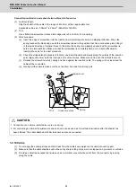
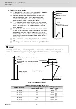
(3) Installing the sensor section
[1] Prepare the notched fitting section at the machine side's installation
position to be of the specified dimensions in advance.
[2] With the sensor installation seat's R section butted against the
notched fitting section, fix the sensor installation seat with a
mounting screw (M4 × 0.8 screws). A locking agent should be
applied on the mounting screw before it is tightened.
[3] Fix the sensor with its R section butted against the notched fitting
section so that the position relation between the detection gear and
sensor is kept constant. This ensures favorable accuracy of the
sensor installation.
[4] Keep the deviation of the sensor center and outer diameter center of
the detection gear to ±0.25mm or less. If the center deviation cannot
be directly measured, set so that the dimension from the sensor
installing surface to the outer diameter edge of the detection gears is
19.0±0.25mm. (Some detection gears have thickness at the inner
diameter section.)
[5] Make sure that force is not constantly applied on the sensor's lead
wires.
[6] Check the gap between the encoder sensor and the gear (0.3±0.05mm).
Shape of notched fitting section
Installing dimension of the sensor section
POINT
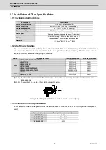
To install the sensor section, the notched fitting section on the machine side must have the specified dimensions.
The sensor's installation accuracy is assured by adjusting the outside dimensions of the notched fitting section.
Sensor series type
Screw holes’ height from the
rotation center (mm)
Notched fitting section's outer
diameter (mm)
TS5690N64xx
36.7
Φ
59.4
-0.030
-0.070
TS5690N90xx
47.1
Φ
79.2
0
-0.040
TS5690N12xx
62.3
Φ
108.8
+0.025
-0.015
TS5690N19xx
87.9
Φ
159.4
+0.005
-0.035
TS5690N25xx
113.5
Φ
210.2
+0.040
0
13.0mm
19.0mm ± 0.25mm
Sensor installation surface
Sensor installation seat
Lead wire
Installing the detector
R section
Z phase
side
Run-out of the outer
diameter
0
.02
mm
o
r l
e
s
s
To the end of the outer diameter
39mm
3.0mm
Butt the R section of the sensor installation seat
against here
Butt the back side of the sensor installation seat
against here
Notched section's
outer diameter
Notched section's
outer diameter
Screw holes' height
from the rotation center
2-M4×0.8 screw
Summary of Contents for MDS-E
Page 1: ......
Page 3: ......
Page 15: ......
Page 17: ......
Page 19: ......
Page 21: ......
Page 31: ......
Page 32: ...1 IB 1501229 F 1 Installation ...
Page 76: ...45 IB 1501229 F 2 Wiring and Connection ...
Page 132: ...101 IB 1501229 F 3 Safety Function ...
Page 142: ...111 IB 1501229 F 4 Setup ...
Page 277: ...MDS E EH Series Instruction Manual 4 Setup 246 IB 1501229 F ...
Page 278: ...247 IB 1501229 F 5 Servo Adjustment ...
Page 351: ...MDS E EH Series Instruction Manual 5 Servo Adjustment 320 IB 1501229 F ...
Page 352: ...321 IB 1501229 F 6 Spindle Adjustment ...
Page 404: ...373 IB 1501229 F 7 Troubleshooting ...
Page 455: ...MDS E EH Series Instruction Manual 7 Troubleshooting 424 IB 1501229 F ...
Page 456: ...425 IB 1501229 F 8 Maintenance ...
Page 475: ...MDS E EH Series Instruction Manual 8 Maintenance 444 IB 1501229 F ...
Page 476: ...445 IB 1501229 F 9 Power Backup System ...
Page 494: ...463 IB 1501229 F 10 Appx 1 Cable and Connector Assembly ...
Page 504: ...473 IB 1501229 F 11 Appx 2 D A Output Specifications for Drive Unit ...
Page 514: ...483 IB 1501229 F 12 Appx 3 Protection Function ...
Page 523: ...MDS E EH Series Instruction Manual 12 Appx 3 Protection Function 492 IB 1501229 F ...
Page 524: ...493 IB 1501229 F 13 Appx 4 Compliance to EC Directives ...
Page 528: ...497 IB 1501229 F 14 Appx 5 EMC Installation Guidelines ...
Page 540: ...509 IB 1501229 F 15 Appx 6 Higher Harmonic Suppression Measure Guidelines ...
Page 550: ......
Page 554: ......

