


MDS-E/EH Series Instruction Manual
1 Installation
39
IB-1501229-F
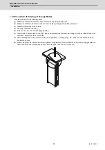
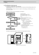
(4) Installation accuracy diagnosis for spindle side PLG encoder
[1] Outline
In this section, check if the installation polarity of spindle side PLG encoder corresponds to the parameter setting,
and the gap between the gear and the sensor is appropriate. In a full-closed loop control where the encoder is also
installed on the spindle side, it is controlled based on the feedback of the spindle side encoder during the speed
command operation (S command). Do not command a normal spindle operation before confirming the installation
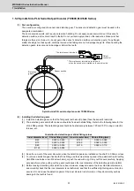
accuracy of the spindle side encoder.Spindle side PLG encoders (TS5690 Series) have the specified gap from the
gear by installing the sensor section on the machine-notched fitting section. Whether a signal is detected correctly
or not can be confirmed using the servo diagnosis screen on NC while rotating the spindle motor in an open loop
control.
[2] Confirmation of encoder installation polarity
Open the drive monitor/spindle unit on the NC Diagnosis screen, and display "Machine position", "Motor end FB"
and "FB error". Confirm that "Machine position" and "Motor end FB" are counted on the same polarity, and that "FB
error" is not cumulated while rotating the spindle by hand. When the polarity of "Machine position" and "Motor end
FB" is different and "FB error" is cumulated, change the setting of #13017/bit4 (SP017/bit4). Set the spindle
parameter so that the spindle system is in a full-closed loop control during this confirmation.
- #13019 (SP019) Set the encoder resolution of spindle side PLG encoder correctly
- #13031 (SP031) Set to full closed loop control (6200)
[3] Confirmation of encoder installation accuracy
Whether the gap between the sensor section and the gear is ensured correctly or not can be confirmed using the
servo diagnosis screen, [PLG diagn] on NC while rotating the spindle motor in an open loop control. Confirm it
according to the following procedures.
1)
Set the spindle parameter #13018/bit1 (SP018/bit1) to 1 to enable an open loop control.
2)
Turn the NC and drive unit power OFF and disconnect the motor side encoder cable only. After that, turn
the power ON again.
3)
Rotate the spindle by inputting 100r/min command. Although this is the same as normal S command
operation, neither the spindle side encoder feed back or the motor side encoder feed back is used for the
motor control on the spindle drive unit since the open loop control is set with the spindle parameter.
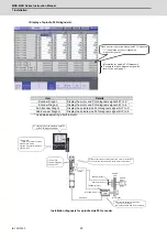
4)
Switch to the [Servo diagn] menu on the NC maintenance screen and change from [Spindle unit] to [PLG
diagn]. When all the diagnosis signal bits are constantly at "0", the installation of PLG encoder is normal.
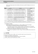
When the diagnosis signal bit is "1", the result of diagnosis is abnormal. Perform troubleshooting following
"[4] Diagnosis and remedy" by reference to the error details and main cause.
5)
Set the spindle parameter #13018/bit1 (SP018/bit1) to 0 again and finish the open loop control after
stopping the spindle with stop command.
6)
Turn the NC and spindle drive unit power OFF, and reconnect the motor side encoder cable as it was.
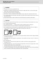
CAUTION
Do not operate the spindle before performing this installation accuracy diagnosis.
If operated with an improperly installed spindle side PLG encoder, the spindle motor may rotate at high speed.
Always perform this diagnosis before normal operation.
CAUTION
The spindle PLG diagnosis is only performed during the open loop control operation.Diagnosis screen is displayed even
during the normal operation, however, the error detection ("1" display) will not be performed.
Summary of Contents for MDS-E
Page 1: ......
Page 3: ......
Page 15: ......
Page 17: ......
Page 19: ......
Page 21: ......
Page 31: ......
Page 32: ...1 IB 1501229 F 1 Installation ...
Page 76: ...45 IB 1501229 F 2 Wiring and Connection ...
Page 132: ...101 IB 1501229 F 3 Safety Function ...
Page 142: ...111 IB 1501229 F 4 Setup ...
Page 277: ...MDS E EH Series Instruction Manual 4 Setup 246 IB 1501229 F ...
Page 278: ...247 IB 1501229 F 5 Servo Adjustment ...
Page 351: ...MDS E EH Series Instruction Manual 5 Servo Adjustment 320 IB 1501229 F ...
Page 352: ...321 IB 1501229 F 6 Spindle Adjustment ...
Page 404: ...373 IB 1501229 F 7 Troubleshooting ...
Page 455: ...MDS E EH Series Instruction Manual 7 Troubleshooting 424 IB 1501229 F ...
Page 456: ...425 IB 1501229 F 8 Maintenance ...
Page 475: ...MDS E EH Series Instruction Manual 8 Maintenance 444 IB 1501229 F ...
Page 476: ...445 IB 1501229 F 9 Power Backup System ...
Page 494: ...463 IB 1501229 F 10 Appx 1 Cable and Connector Assembly ...
Page 504: ...473 IB 1501229 F 11 Appx 2 D A Output Specifications for Drive Unit ...
Page 514: ...483 IB 1501229 F 12 Appx 3 Protection Function ...
Page 523: ...MDS E EH Series Instruction Manual 12 Appx 3 Protection Function 492 IB 1501229 F ...
Page 524: ...493 IB 1501229 F 13 Appx 4 Compliance to EC Directives ...
Page 528: ...497 IB 1501229 F 14 Appx 5 EMC Installation Guidelines ...
Page 540: ...509 IB 1501229 F 15 Appx 6 Higher Harmonic Suppression Measure Guidelines ...
Page 550: ......
Page 554: ......


