MDS-E/EH Series Instruction Manual
1 Installation
43
IB-1501229-F
1.6 Noise Measures
Noise includes "propagation noise" generated from the power supply or relay, etc., and propagated along a cable
causing the power supply unit or drive unit to malfunction, and "radiated noise" propagated through air from a peripheral
device, etc., and causing the power supply unit or drive unit to malfunction.
Always implement these noise measures to prevent the peripheral devices and unit from malfunctioning. The measures
differ according to the noise propagation path, so refer to the following explanation and take appropriate measures.
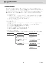
(1) General noise measures
(a) Avoid laying the drive unit's power line and signal wire in a parallel or bundled state. Always separate these
wires. Use a twisted pair shielded wire for the encoder cable and signal wires such as the communication
cable connected with the NC unit, and accurately ground the devices.
(d) Ground the shield of the servo encoder's cable with a cable clamp.
(c) Accurately ground the AC reactor.
(2) Propagation noise measures
Take the following measures when noise generating devices are installed and the power supply unit or drive unit
could malfunction.
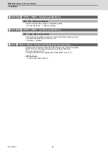
(a) Install a surge killer on devices (magnetic contacts, relays, etc.) which generate high levels of noise.
(b) Install a power line filter in the stage before the power supply unit.
(c) Install a ferrite core on the signal wire.
(d) Ground the shield of the servo encoder's cable with a cable clamp.
(e) Wire the spindle PLG encoder cable away from other wires.
(3) Measures against radiated noise
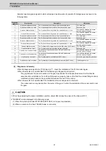
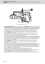
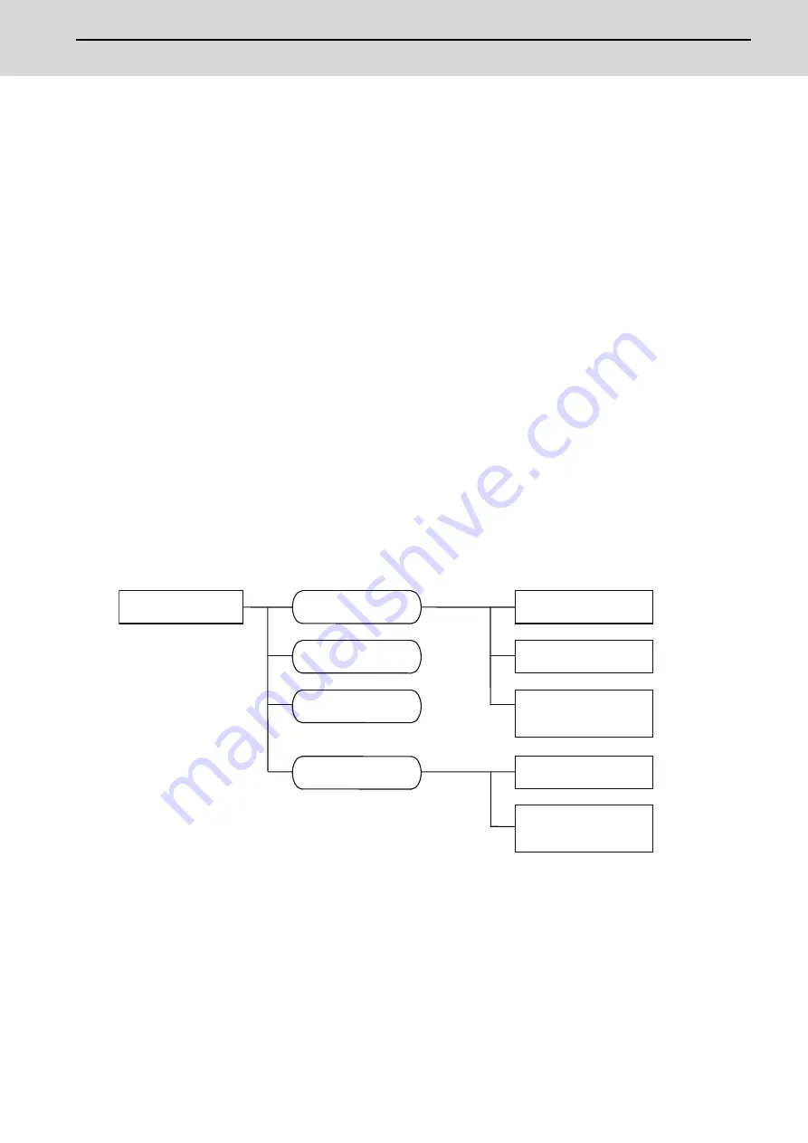
The types of propagation paths of the noise and the noise measures for each propagation path are shown below.
Noise generated from
drive unit
Noise directly radiated
from drive unit
Airborne
propagation noise
Path [1]
Noise radiated from
power line
Magnetic induction
noise
Path [2]
Path [4]
and [5]
Noise radiated from
servo motor/spindle motor
Static induction
noise
Path [3]
Path [6]
Noise propagated over
power line
Cable propagation
noise
Path [7]
Noise lead in from
grounding wire by
leakage current
Path [8]
Summary of Contents for MDS-E
Page 1: ......
Page 3: ......
Page 15: ......
Page 17: ......
Page 19: ......
Page 21: ......
Page 31: ......
Page 32: ...1 IB 1501229 F 1 Installation ...
Page 76: ...45 IB 1501229 F 2 Wiring and Connection ...
Page 132: ...101 IB 1501229 F 3 Safety Function ...
Page 142: ...111 IB 1501229 F 4 Setup ...
Page 277: ...MDS E EH Series Instruction Manual 4 Setup 246 IB 1501229 F ...
Page 278: ...247 IB 1501229 F 5 Servo Adjustment ...
Page 351: ...MDS E EH Series Instruction Manual 5 Servo Adjustment 320 IB 1501229 F ...
Page 352: ...321 IB 1501229 F 6 Spindle Adjustment ...
Page 404: ...373 IB 1501229 F 7 Troubleshooting ...
Page 455: ...MDS E EH Series Instruction Manual 7 Troubleshooting 424 IB 1501229 F ...
Page 456: ...425 IB 1501229 F 8 Maintenance ...
Page 475: ...MDS E EH Series Instruction Manual 8 Maintenance 444 IB 1501229 F ...
Page 476: ...445 IB 1501229 F 9 Power Backup System ...
Page 494: ...463 IB 1501229 F 10 Appx 1 Cable and Connector Assembly ...
Page 504: ...473 IB 1501229 F 11 Appx 2 D A Output Specifications for Drive Unit ...
Page 514: ...483 IB 1501229 F 12 Appx 3 Protection Function ...
Page 523: ...MDS E EH Series Instruction Manual 12 Appx 3 Protection Function 492 IB 1501229 F ...
Page 524: ...493 IB 1501229 F 13 Appx 4 Compliance to EC Directives ...
Page 528: ...497 IB 1501229 F 14 Appx 5 EMC Installation Guidelines ...
Page 540: ...509 IB 1501229 F 15 Appx 6 Higher Harmonic Suppression Measure Guidelines ...
Page 550: ......
Page 554: ......

