MDS-E/EH Series Instruction Manual
1 Installation
44
IB-1501229-F
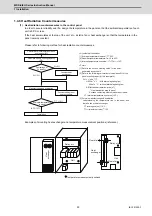
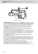
Generated noise of drive system
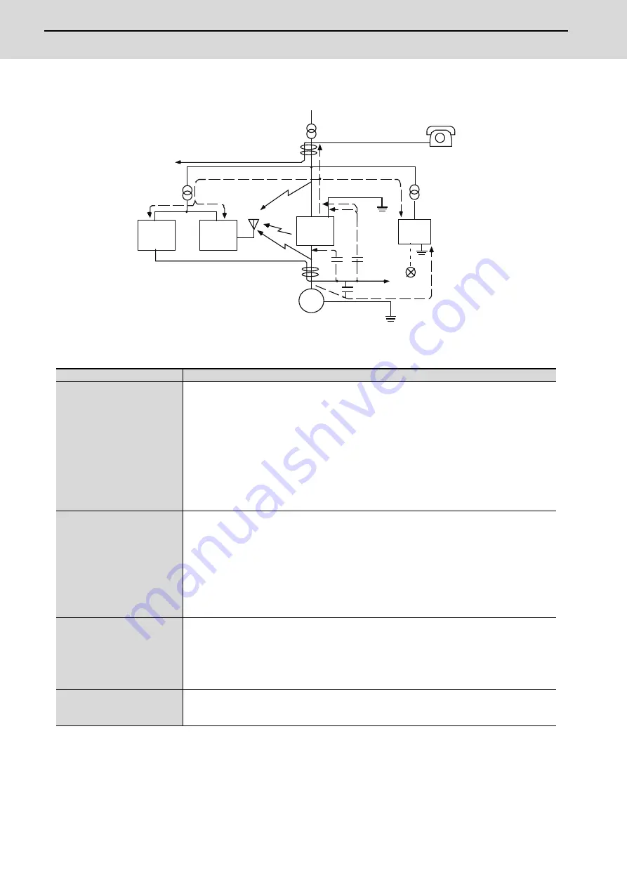
Noise propagation path
Measures
[1] [2] [3]
When devices such as instrument, receiver or sensor, which handle minute signals and
are easily affected by noise, or the signal wire of these devices, are stored in the same
panel as the drive units and the wiring is close, the device could malfunction due to
airborne propagation of the noise. In this case, take the following measures.
(a) Install devices easily affected as far away from the drive units as possible.
(b) Lay devices easily affected as far away from the signal wire of the drive unit as
possible.
(c) Avoid laying the signal wire and power line in a parallel or bundled state.
(d) Insert a line noise filter on the input/output wire or a radio filter on the input to
suppress the noise radiated from the wires.
(e) Use a shield wire for the signal wire and power line, or place in separate metal ducts.
[4] [5] [6]
If the signal wire is laid in parallel to the power line, or if it is bundled with the power line,
the noise could be propagated to the signal wire and cause malfunction because of the
magnetic induction noise or static induction noise. In this case, take the following
measures.
(a) Install devices easily affected as far away from the drive unit as possible.
(b) Lay devices easily affected as far away from the signal wire of the drive unit as
possible.
(c) Avoid laying the signal wire and power line in a parallel or bundled state.
(d) Use a shield wire for the signal wire and power line, or place in separate metal ducts.
[7]
If the power supply for the peripheral devices is connected to the power supply in the
same system as the drive units, the noise generated from the power supply unit could
back flow over the power line and cause the devices to malfunction. In this case, take
the following measures.
(a) Install a radio filter on the power supply unit's power line.
(b) Install a power filter on the power supply unit's power line.
[8]
If a closed loop is created by the peripheral device and drive unit's grounding wire, a
leakage current could flow and cause the device to malfunction.
In this case, change the device grounding methods and the grounding place.
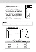
[1]
[2]
[3]
[4]
[5]
[6]
[7]
[8]
Drive
unit
Sensor
Servo motor
Spindle motor
M
Receiver
Instru-
ment
[2]
[7]
Sensor
power
supply
Summary of Contents for MDS-E
Page 1: ......
Page 3: ......
Page 15: ......
Page 17: ......
Page 19: ......
Page 21: ......
Page 31: ......
Page 32: ...1 IB 1501229 F 1 Installation ...
Page 76: ...45 IB 1501229 F 2 Wiring and Connection ...
Page 132: ...101 IB 1501229 F 3 Safety Function ...
Page 142: ...111 IB 1501229 F 4 Setup ...
Page 277: ...MDS E EH Series Instruction Manual 4 Setup 246 IB 1501229 F ...
Page 278: ...247 IB 1501229 F 5 Servo Adjustment ...
Page 351: ...MDS E EH Series Instruction Manual 5 Servo Adjustment 320 IB 1501229 F ...
Page 352: ...321 IB 1501229 F 6 Spindle Adjustment ...
Page 404: ...373 IB 1501229 F 7 Troubleshooting ...
Page 455: ...MDS E EH Series Instruction Manual 7 Troubleshooting 424 IB 1501229 F ...
Page 456: ...425 IB 1501229 F 8 Maintenance ...
Page 475: ...MDS E EH Series Instruction Manual 8 Maintenance 444 IB 1501229 F ...
Page 476: ...445 IB 1501229 F 9 Power Backup System ...
Page 494: ...463 IB 1501229 F 10 Appx 1 Cable and Connector Assembly ...
Page 504: ...473 IB 1501229 F 11 Appx 2 D A Output Specifications for Drive Unit ...
Page 514: ...483 IB 1501229 F 12 Appx 3 Protection Function ...
Page 523: ...MDS E EH Series Instruction Manual 12 Appx 3 Protection Function 492 IB 1501229 F ...
Page 524: ...493 IB 1501229 F 13 Appx 4 Compliance to EC Directives ...
Page 528: ...497 IB 1501229 F 14 Appx 5 EMC Installation Guidelines ...
Page 540: ...509 IB 1501229 F 15 Appx 6 Higher Harmonic Suppression Measure Guidelines ...
Page 550: ......
Page 554: ......

