

MDS-E/EH Series Instruction Manual
2 Wiring and Connection
47
IB-1501229-F
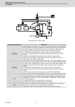
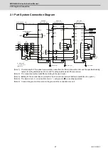
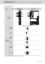
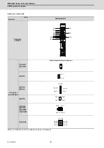
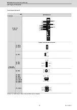
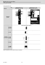
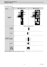
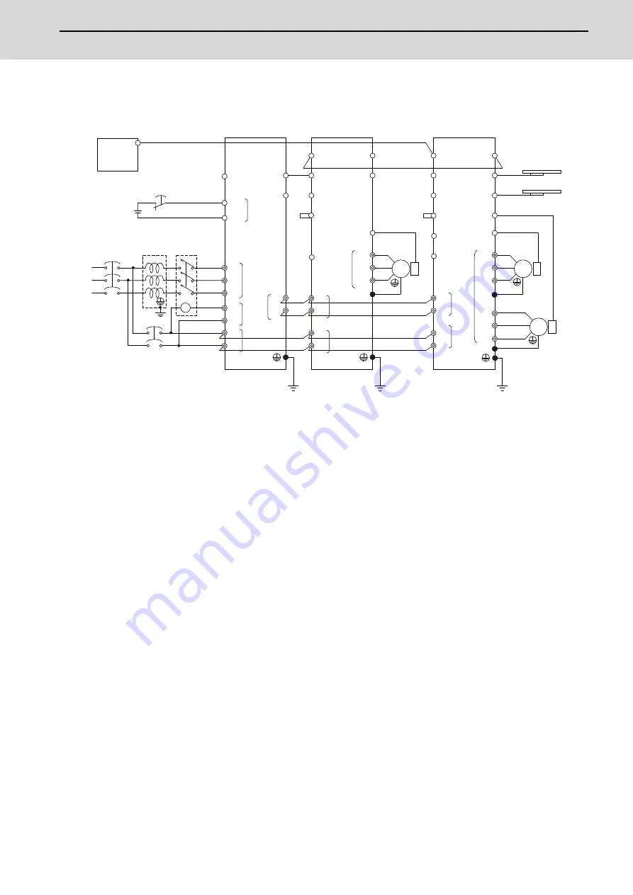
2.1 Part System Connection Diagram
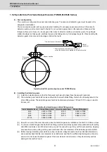
(Note 1) The total length of the optical communication cable from the NC must be within 30m and the specified bending
radius (for wiring inside panel: 25mm, and for wiring outside panel: 50mm) or more.
(Note 2) The connection method will differ according to the used motor.
(Note 3) Battery for the encoder back up is built-in the drive unit. (An external battery is available as an option.)
(Note 4) The main circuit (
◎
) and control circuit (
○
) and ground (
●
) are safely separated.
(Note 5) Connect the ground of the motor to the ground of the connected drive unit.
MC2
OPTH 1,2
T
S
R
CN1A
CN4
CN9
L1
L2
L3
L11
TE3
TE1
CN9
CN1B
L-
CN2
TE1
PLG
CN4
TE3
TE2
L+
L-
L11
L21
TE2
L21
CN3
CN1A
CN4
CN9
CN1B
MU
MV
MW
CN2L
CN2M
LU
LV
LW
TE1
TE3
TE2
L+
L-
L11
L21
CN3L
CN3M
MC
MC1
EMG1
EMG2
(PE)
(PE)
(PE)
(PE)
CN24
CN41
MDS-E/EH
MDS-E/EH
MDS-E/EH
CN23
CN8
CN5
CN8
CN20
CN5
L+
LU
LV
LW
Optical communication cable
24VDC
ۑ
: Control circuit
SH21
cable
AC
reactor
Machine side
encoder
Machine side
encoder
External emergency
stop input
Contactor
Ground (PE)
۔
: Main circuit
Spindle
motor
Motor side
encoder
Motor side
encoder
Servo
motor
Optical communication cable
Mitsubishi CNC
Spindle drive unit
Power supply unit
Ground
Ground
Servo drive unit
Ground
Servo
motor
Circuit
protector
Circuit
protector
ە
: Ground
Summary of Contents for MDS-E
Page 1: ......
Page 3: ......
Page 15: ......
Page 17: ......
Page 19: ......
Page 21: ......
Page 31: ......
Page 32: ...1 IB 1501229 F 1 Installation ...
Page 76: ...45 IB 1501229 F 2 Wiring and Connection ...
Page 132: ...101 IB 1501229 F 3 Safety Function ...
Page 142: ...111 IB 1501229 F 4 Setup ...
Page 277: ...MDS E EH Series Instruction Manual 4 Setup 246 IB 1501229 F ...
Page 278: ...247 IB 1501229 F 5 Servo Adjustment ...
Page 351: ...MDS E EH Series Instruction Manual 5 Servo Adjustment 320 IB 1501229 F ...
Page 352: ...321 IB 1501229 F 6 Spindle Adjustment ...
Page 404: ...373 IB 1501229 F 7 Troubleshooting ...
Page 455: ...MDS E EH Series Instruction Manual 7 Troubleshooting 424 IB 1501229 F ...
Page 456: ...425 IB 1501229 F 8 Maintenance ...
Page 475: ...MDS E EH Series Instruction Manual 8 Maintenance 444 IB 1501229 F ...
Page 476: ...445 IB 1501229 F 9 Power Backup System ...
Page 494: ...463 IB 1501229 F 10 Appx 1 Cable and Connector Assembly ...
Page 504: ...473 IB 1501229 F 11 Appx 2 D A Output Specifications for Drive Unit ...
Page 514: ...483 IB 1501229 F 12 Appx 3 Protection Function ...
Page 523: ...MDS E EH Series Instruction Manual 12 Appx 3 Protection Function 492 IB 1501229 F ...
Page 524: ...493 IB 1501229 F 13 Appx 4 Compliance to EC Directives ...
Page 528: ...497 IB 1501229 F 14 Appx 5 EMC Installation Guidelines ...
Page 540: ...509 IB 1501229 F 15 Appx 6 Higher Harmonic Suppression Measure Guidelines ...
Page 550: ......
Page 554: ......


