
MDS-E/EH Series Instruction Manual
2 Wiring and Connection
63
IB-1501229-F
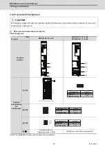
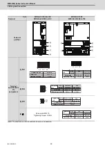
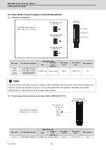
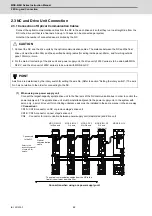
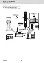
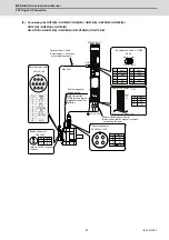
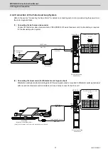
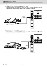
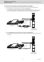
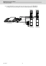
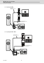
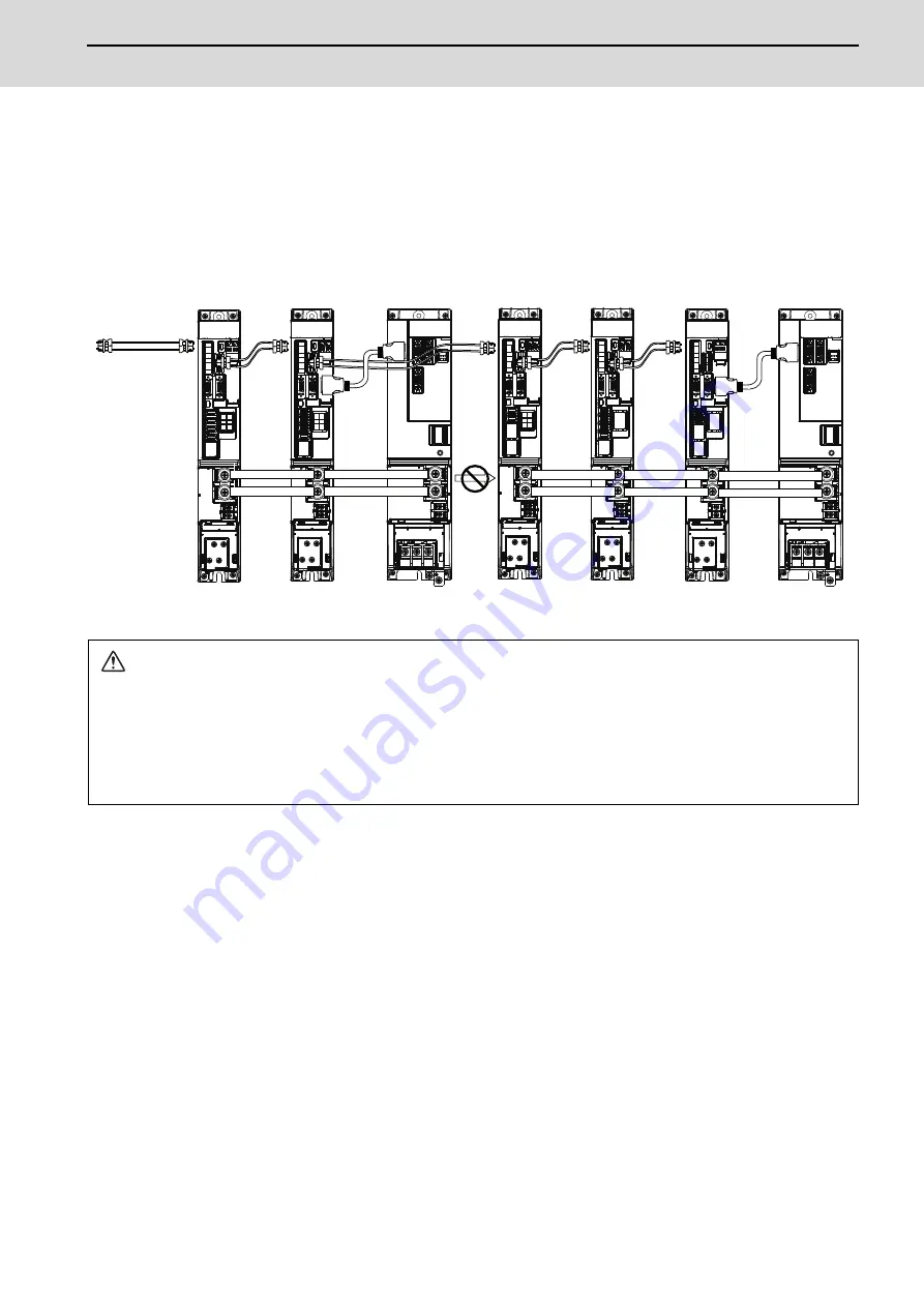
(2) When using two or more power supply units within a single NC communication bus system
Two or more power supply units may be required within a single NC communication bus system if the spindle drive
unit capacity is large. The drive unit receiving power (L+, L-) from each power supply unit must always have NC
communication cable connection at the NC side of each power supply unit. In the NC communication bus
connection example below, power supply [1] cannot supply power (L+, L-) to the 5th axis servo drive unit.
For basic connection information, refer to "(1) When using one power supply unit".
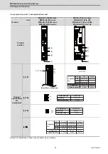
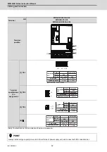
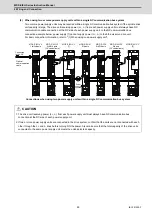
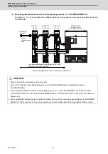
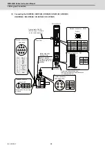
Connections when using two power supply units within a single NC communication bus system
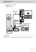
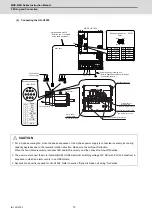
CAUTION
1. The drive unit receiving power (L+, L-) from each power supply unit must always have NC communication bus
connection at the NC side of each power supply unit.
2. If two or more power supply units are connected in the drive system, confirm that the units are not connected with each
other through the L+ and L- lines before turning ON the power. Also make sure that the total capacity of the drive units
connected to the same power supply unit meets the unit's selected capacity.
CN4
CN4
CN4
CN4
Power
cannot be
supplied
Optical
communication
cable
MDS-E/EH-SP
8th axis
(CV control axis)
MDS-E/EH-CV
[2]
MDS-E-SP2
6th/7th axis
MDS-E/EH-V2
1st/2nd axis
MDS-E/EH-V2
3rd/4th axis
(CV control axis)
MDS-E/EH-CV
[1]
MDS-E/EH-V1
5th axis
Connected
to the NC
Summary of Contents for MDS-E
Page 1: ......
Page 3: ......
Page 15: ......
Page 17: ......
Page 19: ......
Page 21: ......
Page 31: ......
Page 32: ...1 IB 1501229 F 1 Installation ...
Page 76: ...45 IB 1501229 F 2 Wiring and Connection ...
Page 132: ...101 IB 1501229 F 3 Safety Function ...
Page 142: ...111 IB 1501229 F 4 Setup ...
Page 277: ...MDS E EH Series Instruction Manual 4 Setup 246 IB 1501229 F ...
Page 278: ...247 IB 1501229 F 5 Servo Adjustment ...
Page 351: ...MDS E EH Series Instruction Manual 5 Servo Adjustment 320 IB 1501229 F ...
Page 352: ...321 IB 1501229 F 6 Spindle Adjustment ...
Page 404: ...373 IB 1501229 F 7 Troubleshooting ...
Page 455: ...MDS E EH Series Instruction Manual 7 Troubleshooting 424 IB 1501229 F ...
Page 456: ...425 IB 1501229 F 8 Maintenance ...
Page 475: ...MDS E EH Series Instruction Manual 8 Maintenance 444 IB 1501229 F ...
Page 476: ...445 IB 1501229 F 9 Power Backup System ...
Page 494: ...463 IB 1501229 F 10 Appx 1 Cable and Connector Assembly ...
Page 504: ...473 IB 1501229 F 11 Appx 2 D A Output Specifications for Drive Unit ...
Page 514: ...483 IB 1501229 F 12 Appx 3 Protection Function ...
Page 523: ...MDS E EH Series Instruction Manual 12 Appx 3 Protection Function 492 IB 1501229 F ...
Page 524: ...493 IB 1501229 F 13 Appx 4 Compliance to EC Directives ...
Page 528: ...497 IB 1501229 F 14 Appx 5 EMC Installation Guidelines ...
Page 540: ...509 IB 1501229 F 15 Appx 6 Higher Harmonic Suppression Measure Guidelines ...
Page 550: ......
Page 554: ......


