5. CONNECTION OF UNIT
5.5 Connection of Power Supply
I
-14
5.5 Connection of Power Supply
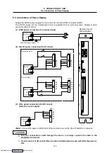
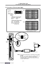
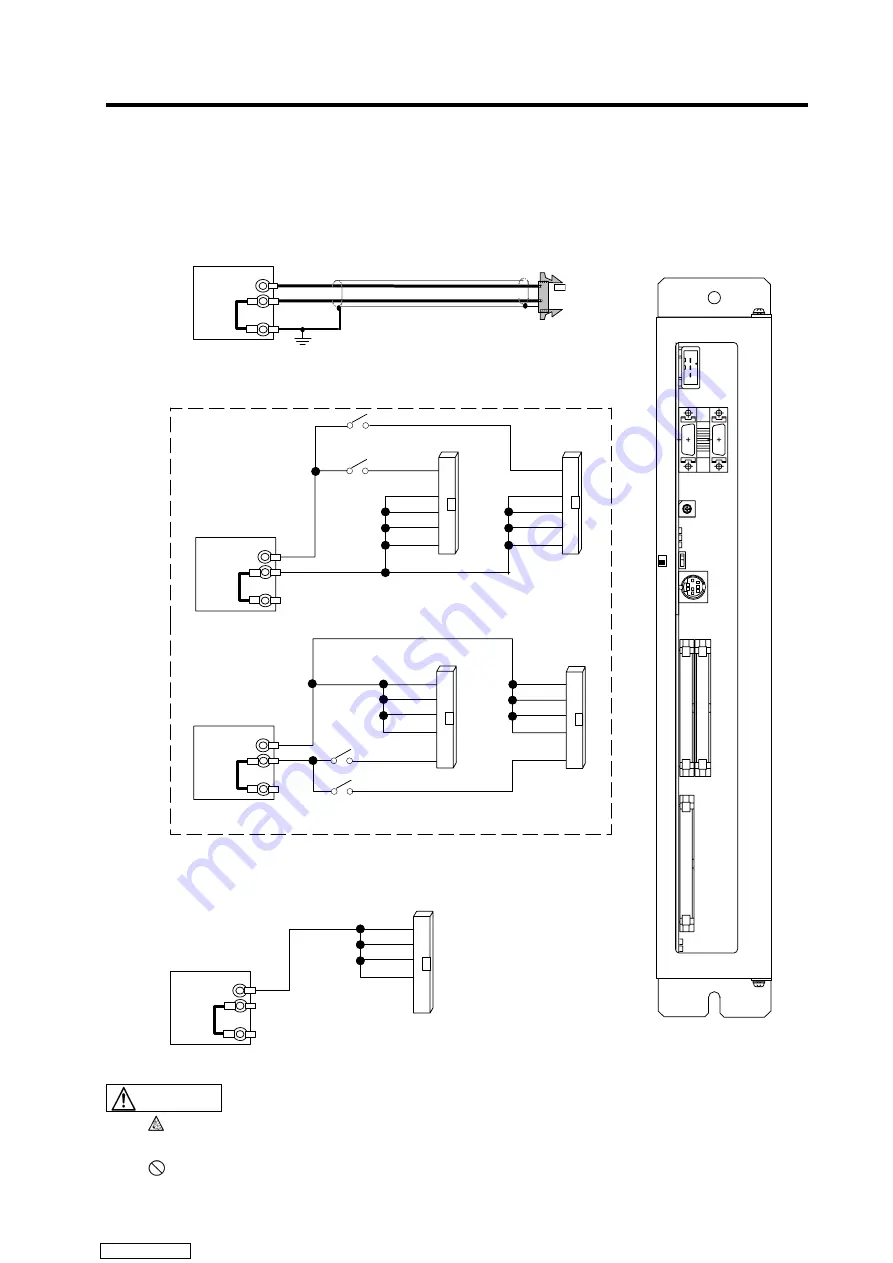
Supply the 24VDC power supply for the control circuit to the DCIN connector (DCIN).
The 24VDC power for the input/output circuit is supplied from an external source. Supply to each
connector (DI-L/-R, DO-L).
(1) DCIN power connection (for control circuit)
Y
FG
24VDC (+)
FG
0V
Stabilized power supply
(2) DI-L/-R power connection (for DI circuit)
DI-R
24VDC (+)
FG
0V
0V
B4
B3
A4
A3
0V
B4
B3
A4
A3
DI-L
DI-R
24VDC (+)
FG
0V
DI-L
+24V
B4
B3
A4
A3
+24V
B4
B3
A4
A3
(For sink input)
(For source input)
(3) DO-L power connection (for DO circuit)
(Fixed to source output)
24VDC (+)
FG
0V
DO-L
+24V
B4
B3
A4
A3
(Note)
Connect the power or GND to all of the common pins on the DI-L/-R and DO-L connector.
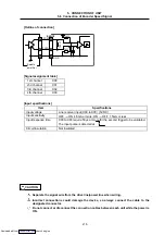
Incorrect connections could damage the device, so always connect the cable to the
designated connector.
Do not connect or disconnect the connection cables between each unit while the power is
ON.
CAUTION
Remote I/O unit
(FCU6-DX561)
DC
IN
EN
C
1
EN
C
2
ST No.
POWER
RU N
CPU-E
STOP
RU N
RI O
ERR1
ERR2
DI
-
R
DI
-
L
PROG
.
PO
R
T
DO
-
L
0
1
2 3
4
567
8
9
ABC
DE
F
Downloaded from


