5. CONNECTION OF UNIT
5.7 Connection of Machine Input/Output Signal
I
-19
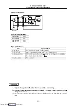
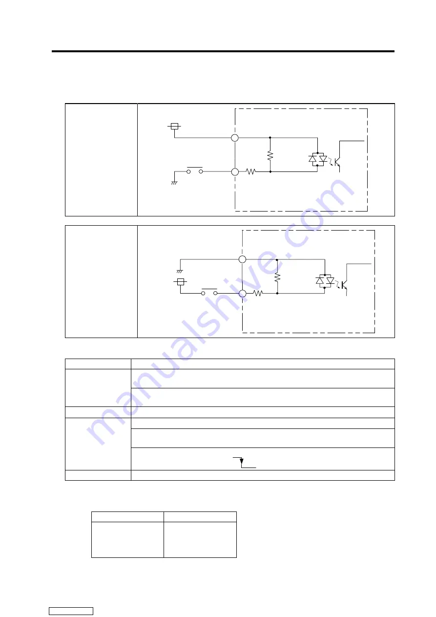
[Outline of input circuit]
The digital signal input circuit includes the sink type and source type. These can be selected with each
connector unit.
Connection method
Sink input
(X04 to X57)
<Octal notation>
DI_COM
X
X04
to
X07:3.3k
Ω
1/2W
X10
to
X57:4.3k
Ω
1/2W
DI_0V
DI_24V
68
0k
Ω
Connection method
Source input
(X04 to X57)
<Octal notation>
DI_0V
DI_24V
DI_COM
X
X04
to
X07:3.3k
Ω
1/2W
X10
to
X57:4.3k
Ω
1/2W
68
0k
Ω
[Input specifications]
Item Specifications
7mA/24VDC +10%, –15% (X04 to X07 sink/source changeover)
(External power supply)
Input voltage,
current
5mA/24VDC +10%, –15% (X10 to X57 sink/source changeover)
(External power supply)
Input sensitivity
OFF
→
ON 4.5mA or more, ON
→
OFF 1.5mA or less
OFF
→
ON Approx. 4ms, ON
→
OFF Approx. 4ms (General input X20 to X57)
X00 to X17 are incorporated in the digital filter. (Can be changed to 0 to 60ms;
note that the minimum is 50µs)
(Note)
Input response
time
X00 to X03 require 50µs or more for the second trigger to be validated.
The input pulse is detected at
.
Circuit insulation
Photo coupler insulation (* Excluding line receiver input)
(Note)
The input filter value can be changed by rewriting the contents of the special data register
D8020 between 0 and 60 using the MOV command, etc. (The contents of D8020 are
automatically set to 10 (10ms) when the power is turned OFF and ON.)
D8020 value
Digital filter value
0
10
to
60
0ms
10ms
to
60ms
Note that in actual use, the minimum C-R filter is provided even on this input, and the value will
not be lower than 50µs (20µs for X00 to X01). Refer to the FX2N Hardware Manual for details.
Downloaded from


