5. CONNECTION OF UNIT
5.7 Connection of Machine Input/Output Signal
I
-20
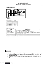
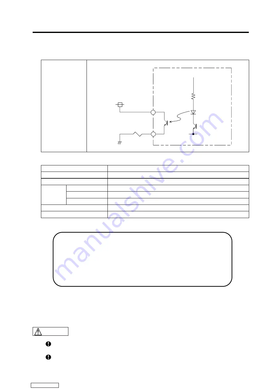
[Outline of output circuit]
The digital signal output circuit is a source type.
Connection method
Source output
(Y00 to Y37)
<Octal notation>
DO_0V
DO_24V
DO_COM
Y
[Output specifications]
Item
Specifications (per point)
Rated voltage, current
5VDC to 30VDC, 0.1A
Response time
0.2ms (at 24VDC, 0.1A energizing)
Resistance load
60mA (200mA for Y0 to Y3)
Inductive load
2.4W/24VDC (7.2W/24VDC for Y0 to Y3)
Maximum
load
Lamp load
0.3W/24VDC (0.9W/24VDC for Y0 to Y3)
Output saturation voltage
1.2V/0.1A
Circuit insulation
Photo coupler insulation
<Caution>
∗
When using an inductive load such as a relay, always connect a diode (voltage
resistance 100V or more, 100mA or more in reverse direction) in parallel to the
load. Note that the device will be damaged if the diode orientation is incorrect.
∗
When using a capacity load such as a lamp, always connect a protective
resistor (R = 150
Ω
) serially to the load to suppress rush currents. (Make sure
that the current is less than the above tolerable current including the
momentary current.)
When using an inductive load such as a relay, always connect a diode in parallel to the
load as a noise countermeasure.
When using a capacity load such as a lamp, always connect a protective resistor serially
to the load to suppress rush currents.
CAUTION
Downloaded from


