2. FAULT DIAGNOSIS
2.2 Troubleshooting
II
-7
(2) Problems related to remote I/O unit (FCU6-DX561)
If any of the following problems occur, all points of the machine input/output data for the remote I/O
unit (FCU6-DX561) will turn OFF or may become unreliable. Thus, detect "Mismatch of input" with
the PLC for another unit (NC).
The communication alarm display "RIOERR1"/"RIOERR2" LED turns ON.
Cause
Remedy
The remote I/O cable (R211) is not
connected, is broken, or the
connector has a contact fault.
Check the connection of the cable (R211) between the base
I/O unit and remote I/O unit (FCU6-DX561).
The remote I/O cable (R211) is
being affected by noise.
Separate the remote I/O cable (R211) from the drive line
and power line.
Always connect the FG wire to the grounding plate.
The station No. setting rotary
switch (SW2) setting is duplicated
with another unit.
Change the base I/O unit, remote I/O unit (FCU6-DX561)
and other remote I/O unit (FCUA-DX1
) station No. rotary
switch settings so that the station numbers are not
duplicated.
A fault has occurred in the internal
circuit of the FX2N-80BMT-NC
card.
Contact the Service Center and have the unit replaced.
The 5VDC output display "POWER" LED turns OFF. (Or, the CPU-E LED lights for an instant.)
Cause
Remedy
The input power is not within the
tolerable range, or there is a fault
in the internal 5V output
generation circuit.
Check that the input voltage is +20V or less, and that the
voltage has not dropped for an instant. If the power is
supplied correctly, contact the Service Center.
The CPU error display "CPU-E" turns ON (flickers).
Cause
Remedy
If the CPU does not run properly
because inductive foreign matter
has entered or because of
abnormal noise from an external
source, or if the operation cycle
exceeds 200ms, the watch dog
timer error will occur and cause
this LED to turn ON.
If the watch dog timer error has occurred, error code 6105
will be stored when D8061 is monitored with a peripheral
device. Review the program to see whether the operation
cycle is too long. (Monitor D8012 to find the maximum
operation cycle.)
Note that if the problem is caused by any other factor, a
communication error will occur and online operations will not
be possible when a peripheral device is connected.
Check for the presence of an abnormal noise generation
source and for the entry of inductive foreign matter.
If this LED changes from a stable light to a flicker as a result
of the inspection, check the program. (Check for circuit
errors and syntax errors with the peripheral device's
program check function.)
If the "CPU-E" LED is still ON after completing all
inspections, contact the Service Center.
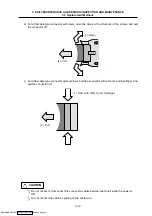
Do not apply voltages other than those indicated in this manual on the connector.
Doing so may lead to destruction or damage.
Incorrect connections may damage the devices, so connect the cables to the specified
connectors.
Do not connect or disconnect the connection cables between each unit while the power is
ON.
Do not connect or disconnect the PCBs while the power is ON.
CAUTION
Downloaded from

