Chapter 9 Setup
9–16
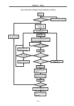
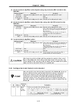
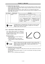
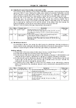
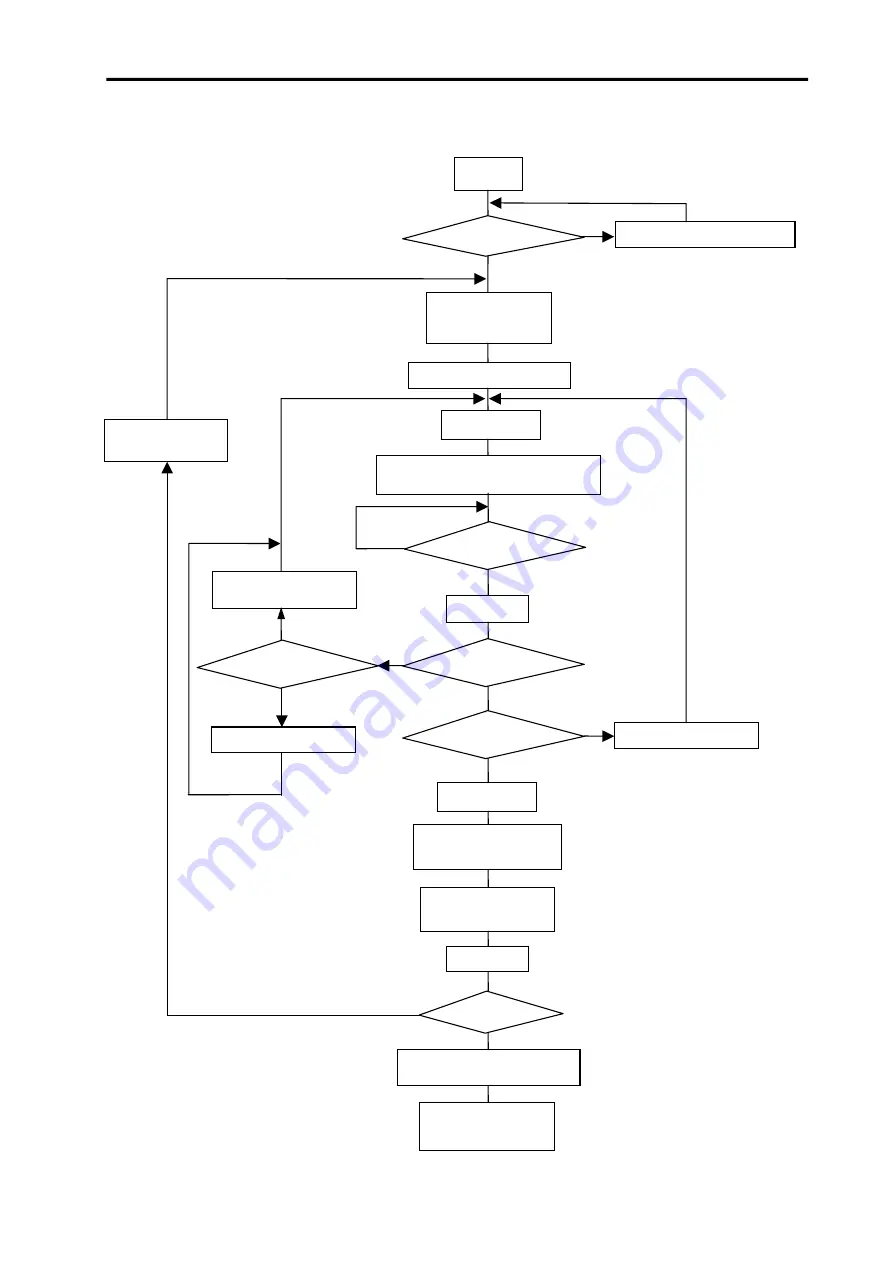
Flow chart for DC excitation and pole shift amount setting
Y
Start of
adjustment
Set SV061: –250
SV062:
–250
SV063: 500
Set SV034/dcd to "1"
Release the
emergency stop
Confirm the motor movement and NC
Servo Monitor MAX CURRENT 2 value.
Emergency
stop
Increase the SV062
setting values
Increase the SV061,
SV062 setting values
Confirm that the motor's
primary side moves to
the end
Confirm Rn on the NC
Absolute Position Motor
Set the Rn display value in
SV028, and SV034/dcd to "0"
Reboot the NC power,
and carry out normal
operation.
Is the polarity
correct?
SV061 = SV062
?
Has a time
exceeding SV063 setting
value passed?
Cycle counter = 0?
Change SV017/fdir
(Change the polarity)
Move the motor's primary side.
Y
N
N
Y
Y
N
Y
N
Did the motor not move?
N
Y
MAX CURRENT
2 value < 100?
N
Check the connection
Release the
emergency stop
Emergency
stop

