Contents
ii
Page
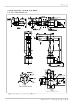
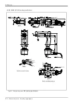
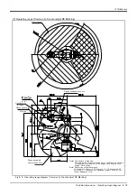
3.3.1 Outside dimensions ....................................................................................................................................................... 3-42
3.3.2 Installation dimensions ................................................................................................................................................. 3-44
3.3.3 Cable lead-in and dimension ..................................................................................................................................... 3-46
3.5 Dedicated input/output ...................................................................................................................................................... 3-48
3.6 Emergency stop input and output etc. ......................................................................................................................... 3-50
3.6.1 Connection of the external emergency stop ...................................................................................................... 3-50
3.6.2 Special stop input(SKIP) ............................................................................................................................................. 3-53
3.6.3 Door switch function .................................................................................................................................................... 3-55
3.6.4 Enabling device function ............................................................................................................................................. 3-55
3.8 Magnet contactor control connector output (AXMC) for addition axes ........................................................ 3-58
3.9 Options ....................................................................................................................................................................................... 3-60
(1) Teaching pendant (T/B) ......................................................................................................................................... 3-61
(2) Pneumatic hand interface ...................................................................................................................................... 3-64
(3) Parallel I/O interface ............................................................................................................................................... 3-66
(4) External I/O cable ..................................................................................................................................................... 3-72
(5) Parallel I/O unit ......................................................................................................................................................... 3-74
(6) External I/O cable ..................................................................................................................................................... 3-82
(7) Personal computer cable ....................................................................................................................................... 3-84
(8) CC-Link interface ..................................................................................................................................................... 3-85
(9) Extension memory cassette ................................................................................................................................. 3-88
(10) RT ToolBox2/RT ToolBox2 mini ...................................................................................................................... 3-89
(11) Instruction Manual(bound edition) ................................................................................................................... 3-91
4.1 List of commands .................................................................................................................................................................. 4-93
4.2 List of parameters ................................................................................................................................................................. 4-96
6.1.1 Self-diagnosis stop functions ................................................................................................................................... 6-99
6.1.2 External input/output signals that can be used for safety protection measures ........................... 6-100
6.1.3 Precautions for using robot .................................................................................................................................... 6-100
6.1.4 Safety measures for automatic operation ........................................................................................................ 6-101
6.1.5 Safety measures for teaching ............................................................................................................................... 6-101
6.1.6 Safety measures for maintenance and inspections, etc. ........................................................................... 6-101
6.1.7 Examples of safety measures ................................................................................................................................ 6-102


