3 Controller
Names of each part 3-38
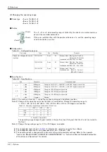
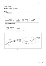
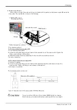
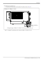
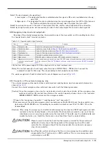
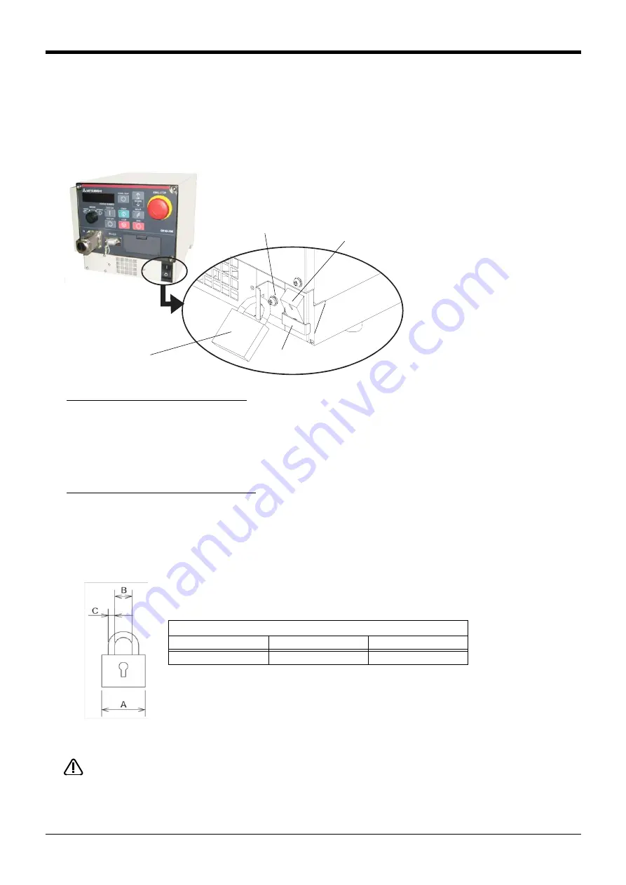
(1) Padlock specification
If the robot is not used, the power switch can be locked with the padlock so that power supply ON cannot be
done easily. The specification is shown in the following.
Fig.3-2 : Operation lock of the power switch (CR1DA-700 series)
The servo will turn OFF when the controller [MODE] switch is changed.
Note that axes not provided with brakes could drop with their own weight.
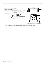
Dimension of the padlock
Dimension
A
B
C
25mm
14mm
4mm or less
The lock device which can be used
Lock plate fixed screw
POWER switch
Lock plate
Padlock (prepare by customer)
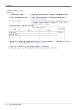
<The operation method>
(1) The lock method (power supply OFF)
1) Turn OFF the power switch.
2) Loosen the lock plate fixing screw and make it slide upwards (cover the power switch). Tighten the
fixing screw certainly in that position.
3) Install the padlock (customer preparation) to the hole of the lock plate, and lock it.
The lock is completion
(2) The release method (power supply ON)
1) Remove the padlock.
2) Loosen the lock plate fixing screw and make it slide downward (position which does not cover the
power switch). Tighten the fixing screw certainly in that position.
Lock release is completion.
Enlarged
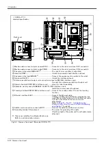
< CR1DA-700 series >
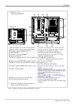
CE marking specification
CAUTION

