


System overview
Robot CPU (SQ series only)
SD-/SQ series
2 - 15
2.4
Robot CPU (SQ series only)
The control units of the SQ series have an external CPU, which can be added to an already existing
SQ system.
Always make sure to connect the EMI line, otherwise the EMERGENCY-OFF state is always enabled.
The maximum permissible cable length is 30 m.
Lay the cable in a cable channel or fix the cable near to the CPU to ensure a secure connection
with plugs CN1 and CN2.
The catch is only used to simplify the installation process. Fix the CPU using the fixing screw on the rack.
Use an external battery as otherwise the program in the SRAM, the parameters, the home position
data etc. will be lost.
R001435E
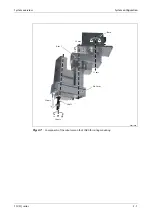
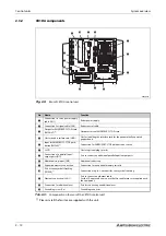
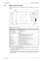
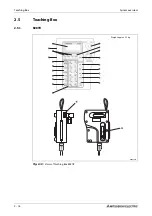
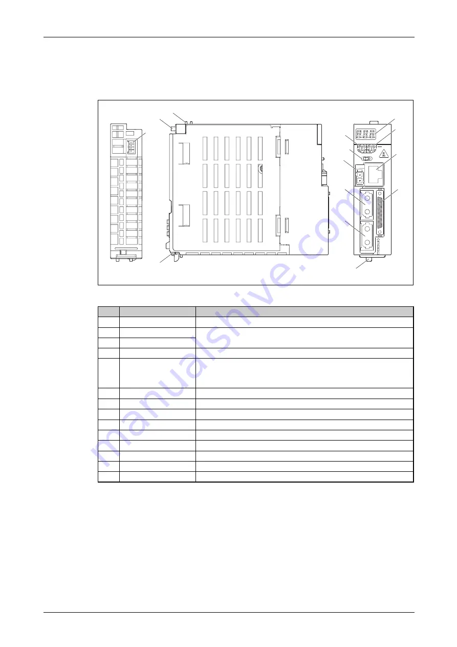
Fig. 2-13:
Robot CPU Q172DRCPU
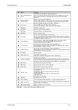
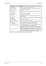
No.
Name
Function
7-segment LED display
Status and alarm display
Code switch SW1
Setting the operating mode
Must be set to "0".
Code switch SW2
[RUN/STOP] selector switch
Not used
EMI
EMERGENCY-STOP input
All servo motors can be stopped simultaneously via this input.
EMI ON (stop): EMERGENCY-STOP enabled
EMI OFF (connect 24 V DC): EMERGENCY-STOP disabled
CN1
Connection of control unit
CN2
Connection of an additional axis (up to 8 axes)
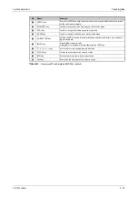
Lock
The locking lever releases the plug when installed in the rack.
Catch
Used to fix the CPU to the rack
Fixing screw
Screw to fix the CPU to the rack (M3 x 13)
Catch
Used to fix the CPU to the rack
Battery connection
Connection for Q170DBATC battery unit
DISPLAY I/F
Connection for the Teaching Box (R56TB)
TU I/F
Connection for an RS422 connection to the control unit
Tab. 2-7:
Overview of robot CPU components
8
4
0
C
0
8
C
4
BAT
FRONT
CN
2
CN
1
EMI
CAUTION
STOP
RUN
1
2
SW
Q172DRCPU
ACFAIL
RIO
MPG
TU I
/F
DI
SPL
A
Y
I/F
Summary of Contents for MELFA RH-12SDH Series
Page 2: ......
Page 4: ......
Page 6: ......
Page 16: ...Contents X ...
Page 22: ...Performance Level PL compliant with EN ISO 13849 1 Introduction 1 6 ...
Page 44: ...Teaching Box System overview 2 22 ...
Page 74: ...Grounding the robot system Installation 3 30 ...
Page 88: ...Teaching Box connection Connection 4 14 ...
Page 98: ...Calibrate the robot system Startup 5 10 ...
Page 114: ...Instructions on maintenance Troubleshooting and maintenance instructions 7 6 ...
Page 134: ...Dimensions Annex A 20 ...
Page 136: ...A 22 Index Annex ...
Page 137: ......
Page 138: ......
Page 139: ......
Page 140: ......
Page 141: ......
Page 142: ......
Page 143: ......
Page 144: ......
Page 145: ......
Page 146: ......
Page 147: ......
Page 148: ......
Page 149: ......
Page 150: ......
Page 151: ......
Page 152: ......
Page 153: ......
Page 154: ......
Page 155: ......
Page 156: ......
Page 157: ......
Page 158: ......
Page 159: ......
Page 160: ......
Page 161: ......
Page 162: ......
Page 163: ......
Page 164: ......
Page 165: ......
Page 166: ......
Page 167: ......
Page 168: ......
Page 169: ......
Page 170: ......
Page 171: ......
Page 172: ......
Page 173: ......
Page 174: ......
Page 175: ......
Page 176: ......
Page 177: ......
Page 178: ......
Page 179: ......
Page 180: ......
Page 181: ......
Page 182: ......
Page 183: ......
Page 184: ......
Page 185: ......


