
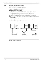


Connection of the connection cable
Connection
4 - 4
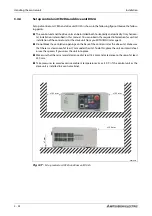
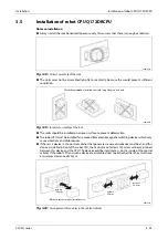
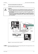
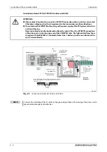
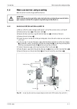
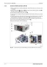
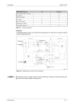
Connection of robot CPU Q172DRCPU to drive unit DU2A
E
ATTENTION:
●
Always place the protective cap on the SSCNETIII connection when no cable is connected.
Otherwise, soiling may lead to an impairment in the transmission and to malfunctions.
●
Do not remove the SSCNETIII cable as long as the power supply of the CPU system or the drive
unit is switched on.
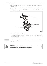
Never look directly into the light emitted from the robot CPU or the SSCNETIII connections
of the drive unit, or into the open end of the SSCNETIII cable. The light emitted from these
complies with the IEC60825-1 standard of laser class 1 and may result in an irritation to the
eyes if viewed directly.
R001509E
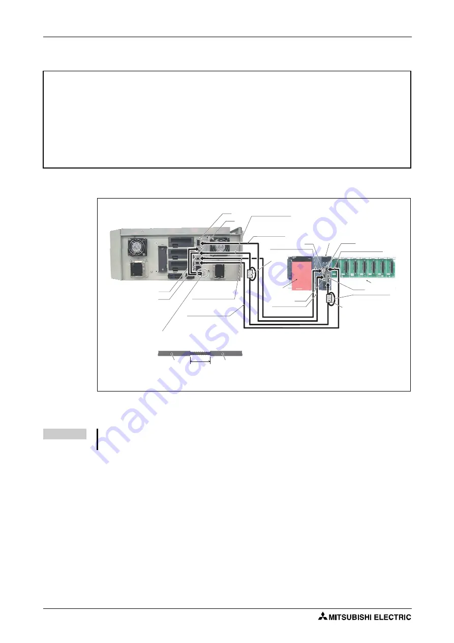
Fig. 4-4:
Connection of robot CPU to drive unit DU2A
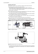
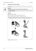
NOTE
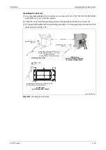
Connect the shielding of the TU cable to the grounding cable on the housing of the drive unit to
prevent electromagnetic disturbances
Remove 20 to 30 mm of wire insulation from the TU cable and
connect the shielding to the grounding terminal on the rear
of the drive unit.
Wire insulation
DU2A drive unit
Robot CPU
Q172DRCPU
Wire insulation
20–30 mm
DISP cable for robot
2Q-DISPCBL 10M
EMI cable for robot
2Q-EMICBL 10M
DCOUT
CNDISP
OPT
CON3
TU cable for robot
2Q-TUCBL 10M
2 ferrite cores
SSCNETIII cable
Ferrite core
CN1
SSCNETIII cable
MR-J3BUS 10M-A
Ferrite core
EMI cable for robot
2Q-EMICBL 10M
EMI
Robot CPU DISP I/F
DISP cable for robot
2Q-DISPCBL 10M
TU cable for robot
2Q-TUCBL 10M
2 ferrite cores
TU I/F
Rack
PLC power
supply
Shielding
Summary of Contents for MELFA RH-12SDH Series
Page 2: ......
Page 4: ......
Page 6: ......
Page 16: ...Contents X ...
Page 22: ...Performance Level PL compliant with EN ISO 13849 1 Introduction 1 6 ...
Page 44: ...Teaching Box System overview 2 22 ...
Page 74: ...Grounding the robot system Installation 3 30 ...
Page 88: ...Teaching Box connection Connection 4 14 ...
Page 98: ...Calibrate the robot system Startup 5 10 ...
Page 114: ...Instructions on maintenance Troubleshooting and maintenance instructions 7 6 ...
Page 134: ...Dimensions Annex A 20 ...
Page 136: ...A 22 Index Annex ...
Page 137: ......
Page 138: ......
Page 139: ......
Page 140: ......
Page 141: ......
Page 142: ......
Page 143: ......
Page 144: ......
Page 145: ......
Page 146: ......
Page 147: ......
Page 148: ......
Page 149: ......
Page 150: ......
Page 151: ......
Page 152: ......
Page 153: ......
Page 154: ......
Page 155: ......
Page 156: ......
Page 157: ......
Page 158: ......
Page 159: ......
Page 160: ......
Page 161: ......
Page 162: ......
Page 163: ......
Page 164: ......
Page 165: ......
Page 166: ......
Page 167: ......
Page 168: ......
Page 169: ......
Page 170: ......
Page 171: ......
Page 172: ......
Page 173: ......
Page 174: ......
Page 175: ......
Page 176: ......
Page 177: ......
Page 178: ......
Page 179: ......
Page 180: ......
Page 181: ......
Page 182: ......
Page 183: ......
Page 184: ......
Page 185: ......


