10
JEP0-IL9555
2. RUN display (Self-monitoring function)
This relay monitors control voltage, electric
circuit, and program data at all time. The RUN LED
(green) lights up in the normal condition.
In the abnormal condition, the RUN LED goes out and
the error message
E r r
is displayed on the
numerical display LED, with the output contact
locked.
3. Numerical display function
By switching the position of the indicator select
switch, following items can be displayed on the
numerical display LED.
①
I
0
current measurement
The display shows the value of zero-sequence
current. The display range is from 0.05A to 1.5A.
(If input current is less than 0.05A, the display
goes out. If input current is more than 1.5A, the
error message
O
.
F
. is displayed.)
②
Pickup
When input zero-sequence current is greater than
or equal to the setting value,
I
. is displayed.
This function can be used for operation value tests.
③
Setting value
It displays the setting condition of the relay
including I
0
operation value and operating time
setting.
④
Frequency setting
It displays the setting condition of frequency in
accordance with the setting switch of SW1.
⑤
Output contact setting (MGR-A3V-R only)
It displays the setting condition of output contact
in accordance with the setting switch of SW2.
The setting is self-hold, the display shows
Ho
..
The setting is auto-reset, the display shows
FU
..
4. Fault record function
①
Display of fault records
When a fault occurs, the relay outputs the
operating signal, and at the same time the input
value of zero-sequence current is recorded. When
the indicator select switch is set to the position
of fault record, the records are displayed starting
from the latest record to the oldest one at
approximately 2 second intervals. The relay can
save the newest five phenomena.
The records are saved in the non-volatile memory,
therefore the records can be read again after
shutting the power off.
Note that the fault record may not be saved if the
auxiliary power supply is turned off soon after
the relay operation.
②
Clearing of fault records
Set indicator select switch to "CLEAR FAULT REC."
and hold for 5s or more, then
O
.
K
. is displayed
and all of the fault record are cleared.
5. Display function of setting change
When a setting is changed, the setting value after
changing is displayed for approx. 3s preferentially.
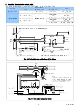
Internal connection diagram
B1
B2
c
b
X0
a
Z1
Z2
Continuous
monitoring
Power circuit
monitoring
Operation
indicator
RUN indicator
Output
contact
X0
Level
assessment
Power supply
P1
P2
I
0
X1
E
Auxiliary
power
supply
X1
Output
contact
a
)
MGR-A3V-R
B1
B2
T1
T2
X0
O1
O2
S2
S1
SO
X0
X0
X1
L
E
Z1
Z2
Continuous
monitoring
Power circuit
monitoring
Operation
indicator
RUN indicator
Output
contact
X0
Level
assessment
Power supply
P1
P2
I
0
Auxiliary
power
supply
X1
Output
contact
b
)
MGR-A3T-R
Fig. 3-2 Internal connection diagram


