
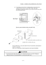

4 - 3
Chapter 4 Installation, Wiring and Maintenance of the Product
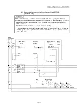
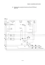
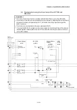
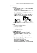
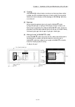
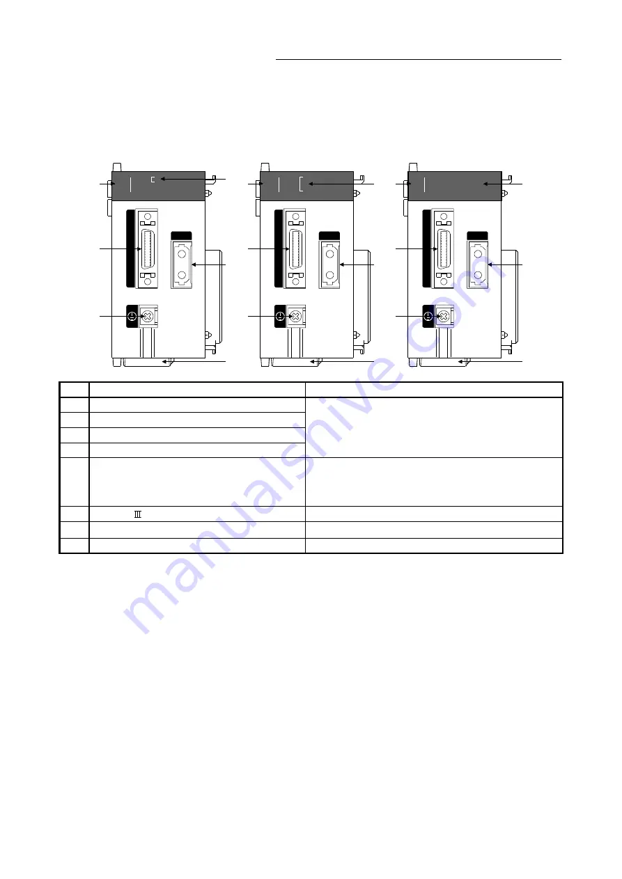
4.1.2 Names of each part
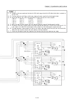
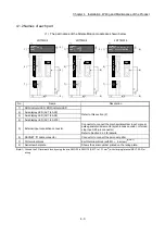
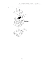
(1) The part names of the Simple Motion module are shown below.
LD77MS2
LD77MS4
LD77MS16
P
U
L
S
E
R
CN1
LD77MS4
RUN
ERR.
AX
1
2
3
4
LD77MS16
RUN
ERR.
AX 1
9 10111213141516
2 3 4 5 6 7 8
P
U
L
S
E
R
CN1
P
U
L
S
E
R
CN1
LD77MS2
RUN
ERR.
AX
1
2
1)
5)
7)
6)
8)
2) 1)
7)
6)
8)
3)
5)
1)
7)
6)
8)
4)
5)
No. Name
Description
1)
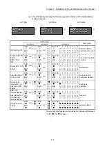
RUN indicator LED, ERR indicator LED
Refer to this section (2).
2)
Axis display LED (AX1 to AX2)
3)
Axis display LED (AX1 to AX4)
4)
Axis display LED (AX1 to AX16)
5)
External input connection connector
Connector to connect the mechanical system input, manual
pulse generator/incremental synchronous encoder, or forced
stop input. (26-pin connector)
Refer to Section 3.4.2 for details.
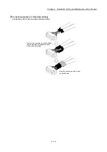
6) SSCNET cable connector
Connector to connect the servo amplifier.
7)
FG terminal block
Earth terminal block (with M3
6 screw)
(Note-1)
8)
Serial number plate
Shows the serial number printed on the rating plate.
(Note-1): Ground the FG terminal block by using the wire AWG20 to AWG16 (0.517 to 1.31 mm
2
) with crimping terminal RAV1.25-3 for
wiring.
Summary of Contents for MELSEC-L Series
Page 2: ......
Page 30: ...MEMO ...
Page 70: ...2 10 Chapter 2 System Configuration MEMO ...
Page 83: ...3 13 Chapter 3 Specifications and Functions MEMO ...
Page 103: ...3 33 Chapter 3 Specifications and Functions MEMO ...
Page 107: ...3 37 Chapter 3 Specifications and Functions MEMO ...
Page 111: ...3 41 Chapter 3 Specifications and Functions MEMO ...
Page 115: ...3 45 Chapter 3 Specifications and Functions MEMO ...
Page 140: ...4 22 Chapter 4 Installation Wiring and Maintenance of the Product MEMO ...
Page 253: ...5 113 Chapter 5 Data Used for Positioning Control MEMO ...
Page 342: ...5 202 Chapter 5 Data Used for Positioning Control MEMO ...
Page 438: ...7 20 Chapter 7 Memory Configuration and Data Process MEMO ...
Page 440: ...MEMO ...
Page 485: ...9 25 Chapter 9 Major Positioning Control MEMO ...
Page 594: ...9 134 Chapter 9 Major Positioning Control MEMO ...
Page 624: ...10 30 Chapter 10 High Level Positioning Control MEMO ...
Page 656: ...11 32 Chapter 11 Manual Control MEMO ...
Page 690: ...12 34 Chapter 12 Expansion Control MEMO ...
Page 798: ...13 108 Chapter 13 Control Sub Functions MEMO ...
Page 866: ...14 68 Chapter 14 Common Functions MEMO ...
Page 884: ...15 18 Chapter 15 Dedicated Instructions MEMO ...
Page 899: ...16 15 Chapter 16 Troubleshooting MEMO ...
Page 1036: ...Appendix 88 Appendices MEMO ...
Page 1039: ......


