


9 - 107
Chapter 9 Major Positioning Control
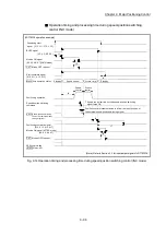
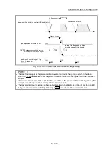
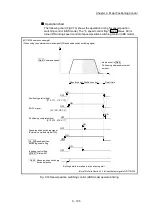
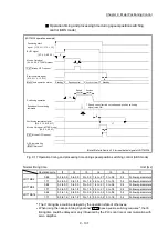
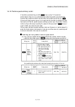
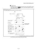
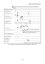
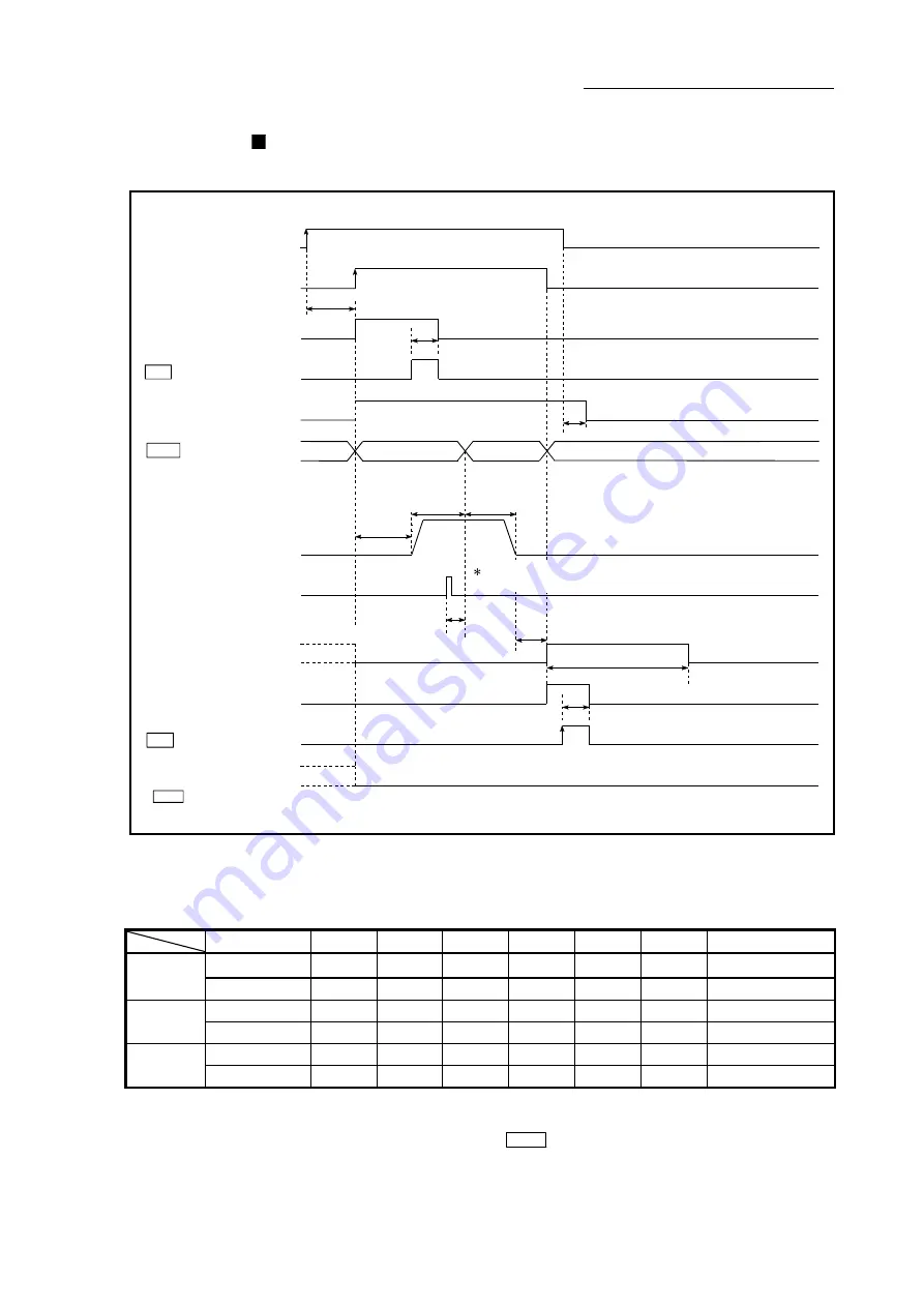
Operation timing and processing time during speed-position switching
control (ABS mode)
[LD77MS4 operation example]
Positioning start
signal [Y10, Y11, Y12, Y13]
BUSY signal
M code ON signal
[X4, X5, X6, X7](WITH mode)
Standby
Speed control
Start complete signal
Positioning operation
Positioning complete signal
M code ON signal (AFTER mode)
t1
t2
t3
t5
t2
t7
Position control
Speed
control
Position
control
Speed-position switching
command
t6
Speed control carried out until speed-position switching
signal turns ON
Md.26 Axis operation status
OPR complete flag
( Md.31 Status: b4)
Cd.7 M code OFF request
Cd.7 M code OFF request
Standby
[XC, XD, XE, XF]
[X10, X11, X12, X13]
[X14, X15, X16, X17]
[X4, X5, X6, X7]
t4
(Note): Refer to Section 3.3 for input/output signal of LD77MS16.
Fig. 9.17 Operation timing and processing time during speed-position switching control (ABS mode)
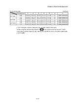
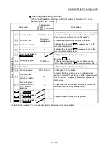
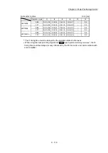
Normal timing time
Unit: [ms]
Operation
cycle
t1 t2 t3 t4 t5 t6
t7
LD77MS2
0.88
0.2 to 0.3 0 to 0.9
0 to 0.9 1.8 to 2.7 0 to 0.9
0.2
Follows parameters
1.77
0.2 to 0.3 0 to 1.8
0 to 1.8 2.5 to 4.1 0 to 1.8
0.2
Follows parameters
LD77MS4
0.88
0.2 to 0.3 0 to 0.9
0 to 0.9 1.8 to 2.7 0 to 0.9
0.2
Follows parameters
1.77
0.2 to 0.3 0 to 1.8
0 to 1.8 2.5 to 4.1 0 to 1.8
0.2
Follows parameters
LD77MS16
0.88
0.3 to 1.4 0 to 0.9
0 to 0.9 2.6 to 3.5 0 to 0.9
0.2
Follows parameters
1.77
0.3 to 1.4 0 to 1.8
0 to 1.8 3.5 to 5.2 0 to 1.8
0.2
Follows parameters
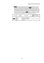
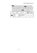
The t1 timing time could be delayed by the operation state of other axes.
When using the near-point dog signal and "
Cd.46
Speed-position switching command
", the t6
timing time could be delayed or vary influenced by the PLC scan time or communication with
servo amplifier.
Summary of Contents for MELSEC-L Series
Page 2: ......
Page 30: ...MEMO ...
Page 70: ...2 10 Chapter 2 System Configuration MEMO ...
Page 83: ...3 13 Chapter 3 Specifications and Functions MEMO ...
Page 103: ...3 33 Chapter 3 Specifications and Functions MEMO ...
Page 107: ...3 37 Chapter 3 Specifications and Functions MEMO ...
Page 111: ...3 41 Chapter 3 Specifications and Functions MEMO ...
Page 115: ...3 45 Chapter 3 Specifications and Functions MEMO ...
Page 140: ...4 22 Chapter 4 Installation Wiring and Maintenance of the Product MEMO ...
Page 253: ...5 113 Chapter 5 Data Used for Positioning Control MEMO ...
Page 342: ...5 202 Chapter 5 Data Used for Positioning Control MEMO ...
Page 438: ...7 20 Chapter 7 Memory Configuration and Data Process MEMO ...
Page 440: ...MEMO ...
Page 485: ...9 25 Chapter 9 Major Positioning Control MEMO ...
Page 594: ...9 134 Chapter 9 Major Positioning Control MEMO ...
Page 624: ...10 30 Chapter 10 High Level Positioning Control MEMO ...
Page 656: ...11 32 Chapter 11 Manual Control MEMO ...
Page 690: ...12 34 Chapter 12 Expansion Control MEMO ...
Page 798: ...13 108 Chapter 13 Control Sub Functions MEMO ...
Page 866: ...14 68 Chapter 14 Common Functions MEMO ...
Page 884: ...15 18 Chapter 15 Dedicated Instructions MEMO ...
Page 899: ...16 15 Chapter 16 Troubleshooting MEMO ...
Page 1036: ...Appendix 88 Appendices MEMO ...
Page 1039: ......


