


3 - 27
Chapter 3 Specifications and Functions
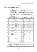
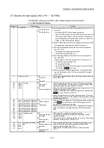
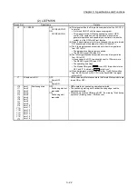
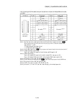
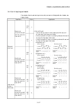
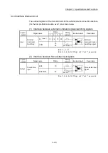
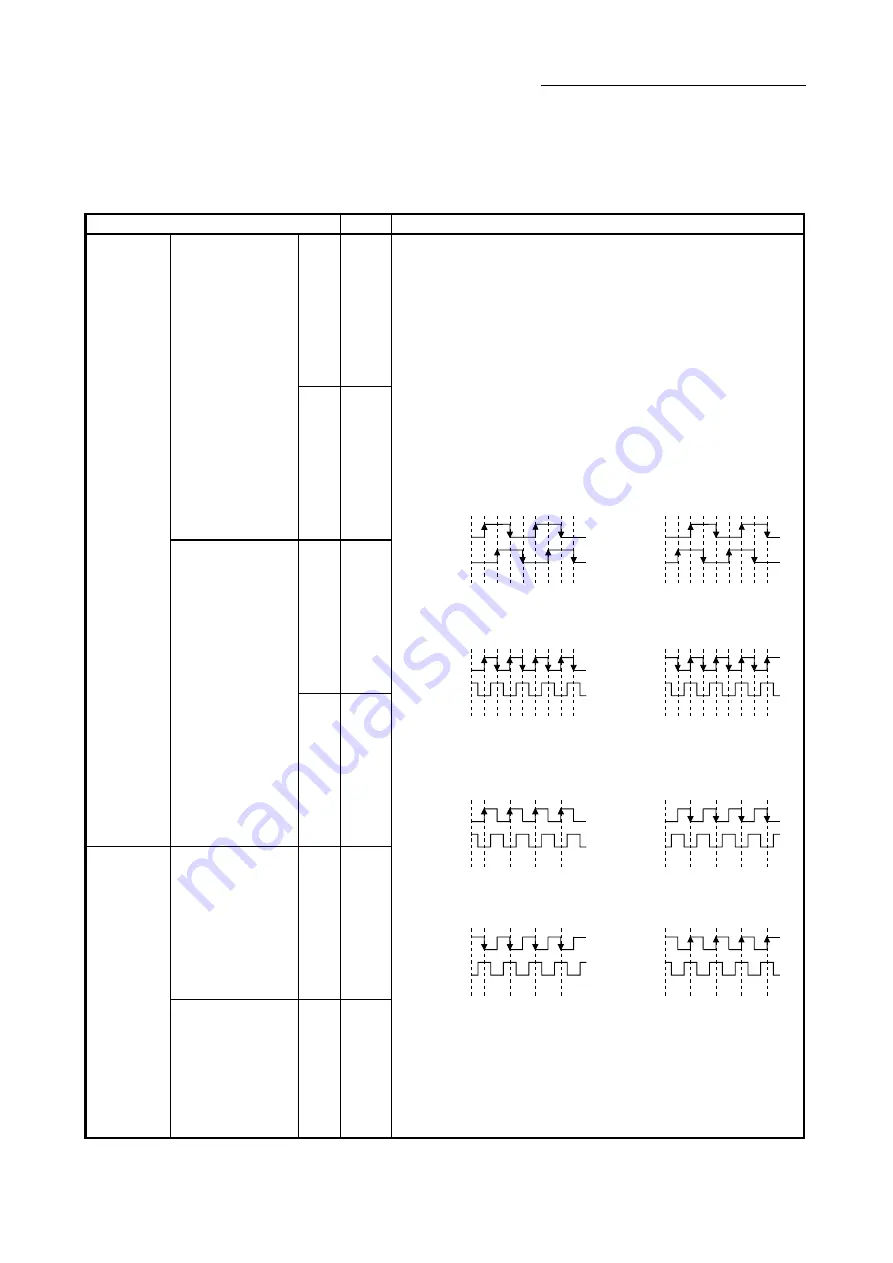
3.4.3 List of input signal details
The details of each external input connection connector of Simple Motion module are
shown below.
Signal name
Pin No.
Signal details
Differential-
output type
Manual pulse
generator/Incremental
synchronous encoder
A phase/PLS
HAH
(A+)
4
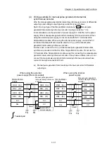
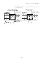
(1) Phase A/Phase B
• Input the pulse signal from the manual pulse generator/incremental
synchronous encoder A phase and B phase.
• If the A phase leads the B phase, the positioning address will increase at
the rising and falling edges of each phase.
• If the B phase leads the A phase, the positioning address will decrease at
the rising and falling edges of each phase.
(a) Magnification by 4
[When increased]
[When decreased]
Positioning
address
Positioning
address
+1
+1
+1+1+1+1+1+1
-1
-1
-1 -1 -1 -1 -1 -1
A phase
B phase
A phase
B phase
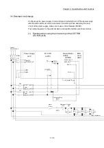
(b) Magnification by 2
[When increased]
[When decreased]
Positioning
address
Positioning
address
+1
+1
+1
+1
-1
-1
-1
-1
A phase
B phase
A phase
B phase
+1
+1
+1
+1
-1
-1
-1
-1
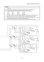
(c) Magnification by 1
1) Positive logic
[When increased]
[When decreased]
Positioning
address
Positioning
address
+1
+1
+1
+1
-1
-1
-1
-1
A phase
B phase
A phase
B phase
2) Negative logic
[When increased]
[When decreased]
Positioning
address
Positioning
address
+1
+1
+1
+1
-1
-1
-1
-1
A phase
B phase
A phase
B phase
HAL
(A-)
5
Manual pulse
generator/Incremental
synchronous encoder
B phase/SIGN
HBH
(B+)
17
HBL
(B-)
18
Voltage-output
type/open-
collector type
Manual pulse
generator/Incremental
synchronous encoder
A phase/PLS
(HA)
(A)
3
Manual pulse
generator/Incremental
synchronous encoder
B phase/SIGN
(HB)
(B)
16
Summary of Contents for MELSEC-L Series
Page 2: ......
Page 30: ...MEMO ...
Page 70: ...2 10 Chapter 2 System Configuration MEMO ...
Page 83: ...3 13 Chapter 3 Specifications and Functions MEMO ...
Page 103: ...3 33 Chapter 3 Specifications and Functions MEMO ...
Page 107: ...3 37 Chapter 3 Specifications and Functions MEMO ...
Page 111: ...3 41 Chapter 3 Specifications and Functions MEMO ...
Page 115: ...3 45 Chapter 3 Specifications and Functions MEMO ...
Page 140: ...4 22 Chapter 4 Installation Wiring and Maintenance of the Product MEMO ...
Page 253: ...5 113 Chapter 5 Data Used for Positioning Control MEMO ...
Page 342: ...5 202 Chapter 5 Data Used for Positioning Control MEMO ...
Page 438: ...7 20 Chapter 7 Memory Configuration and Data Process MEMO ...
Page 440: ...MEMO ...
Page 485: ...9 25 Chapter 9 Major Positioning Control MEMO ...
Page 594: ...9 134 Chapter 9 Major Positioning Control MEMO ...
Page 624: ...10 30 Chapter 10 High Level Positioning Control MEMO ...
Page 656: ...11 32 Chapter 11 Manual Control MEMO ...
Page 690: ...12 34 Chapter 12 Expansion Control MEMO ...
Page 798: ...13 108 Chapter 13 Control Sub Functions MEMO ...
Page 866: ...14 68 Chapter 14 Common Functions MEMO ...
Page 884: ...15 18 Chapter 15 Dedicated Instructions MEMO ...
Page 899: ...16 15 Chapter 16 Troubleshooting MEMO ...
Page 1036: ...Appendix 88 Appendices MEMO ...
Page 1039: ......


