118
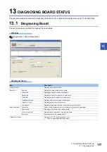
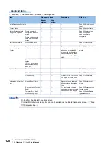
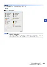
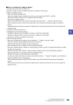
13 DIAGNOSING BOARD STATUS
13.2 Diagnosing CC-Link IE Field Network
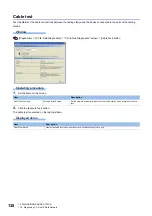
Operating procedure
1.
Click the [Start Monitor] button and start monitoring.
Click the [Stop Monitor] button to stop monitoring.
2.
Set a board channel number of a test target or information display target.
3.
Select a test mode for "Mode".
4.
Click the [Start Test]button.
Start the board test.
5.
Result is displayed in the "Test result" field.
13.2
Diagnosing CC-Link IE Field Network
This section explains a method for checking the CC-Link IE Field Network status of a selected board.
Target station by CC IE Field Utility for the CC-Link IE Field Network diagnostics is as follows.
Station type
Board/Module
Model name
Master station/Local station
CC-Link IE Field Network board
Q80BD-J71GF11-T2
Q81BD-J71GF11-T2
Master/local module
RJ71GF11-T2
RJ71EN71
QJ71GF11-T2
LJ71GF11-T2
Intelligent device station
Head module
LJ72GF15-T2
Ethernet adapter module
NZ2GF-ETB
Remote device stations
Input module
NZ2GF2B1-16D
NZ2GFCE3-16D
NZ2GFCE3-16DE
NZ2GFCM1-16D
NZ2GFCM1-16DE
Output module
NZ2GF2B1-16T
NZ2GF2B1-16TE
NZ2GFCE3-16T
NZ2GFCE3-16TE
NZ2GFCM1-16T
NZ2GFCM1-16TE
Analog input module/Analog output module
NZ2GF2B-60AD4
NZ2GF2B-60DA4
Temperature control module
NZ2GF2B-60TCTT4
NZ2GF2B-60TCRT4
High-speed counter module
NZ2GFCF-D62PD2
Summary of Contents for MELSEC Q80BD-J71GF11-T2
Page 2: ......
Page 6: ...4 Disposal Precautions CAUTION When disposing of this product treat it as industrial waste ...
Page 118: ...116 12 MONITORING MEMO ...
Page 140: ...138 14 MELSEC DATA LINK LIBRARY MEMO ...
Page 142: ...140 15 PROGRAMMING 15 1 Precautions on Programming MEMO ...
Page 243: ...241 I U Utility 83 ...
Page 247: ......


