background image

5  FUNCTIONS

5.5  Reserved Station Specification and Reserved Station Function Disable Function

75

5

5.5

Reserved Station Specification and Reserved 
Station Function Disable Function

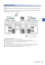
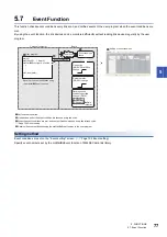
Reserved station specification allows setting of a station that is not actually connected at present but will be connected to the 
network in the future (must be included in the total number of stations for the network). Reserved stations are not detected as 
error stations even though they are not actually connected.
When the reserved station function is disabled, a slave station specified as a reserved station can be canceled temporarily.

Reserved station specification

A slave station can be specified as a reserved station in the "Network Configuration Setting". (

Page 101 Network 

configuration setting)

Reserved station function disable and cancel

This is used when connecting a reserved-status slave station to the network.
Reserved station function disable and cancel is set on "Reserved Station Function Enable" screen. (

Page 134 Reserved 

station function enable)

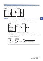
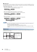
(Not actually connected.)

Master station

(Station No.0)

Slave station

(Station No.1)

Slave station

(Station No.2)

Slave station

(Station No.3)

Network Configuration Setting

Select "Reserved Station".

Reserved station

Summary of Contents for MELSEC Q80BD-J71GF11-T2

Page 1: ...CC Link IE Field Network Interface Board User s Manual For SW1DNC CCIEF B Q80BD J71GF11 T2 Q81BD J71GF11 T2 ...

Page 2: ......

Page 3: ...se rotations or upper lower limit positioning must be configured external to the programmable controller 2 The station to which the board is installed may be disconnected from the data link due to a data link error If this occurs the data output from the station and written to other stations before the error will be held until the station is reconnected to the network until its data link is restar...

Page 4: ...a grounded metal to discharge the static electricity from the human body Failure to do so may cause the board to fail or malfunction Install the board to a personal computer which is compliant with PCI standard or PCI Express standard Page 31 Operating Environment Failure to do so may cause a failure or malfunction Securely insert the board into the PCI slot following the board installation instru...

Page 5: ... power for the system in all phases before installing the board to or removing it from the personal computer Failure to do so may result in electric shock or cause the board to fail or malfunction Do not connect or disconnect any communication cable while power is on Doing so may result in a malfunction CAUTION Thoroughly read the manual and ensure the safety before performing program modification...

Page 6: ...4 Disposal Precautions CAUTION When disposing of this product treat it as industrial waste ...

Page 7: ...e of the PRODUCT in Nuclear Power Plants and any other power plants operated by Power companies and or any other cases in which the public could be affected if any problem or fault occurs in the PRODUCT Railway companies or Public service purposes and or any other cases in which establishment of a special quality assurance system is required by the Purchaser or End User Aircraft or Aerospace Medic...

Page 8: ... other than the method written in the troubleshooting Page 141 TROUBLESHOOTING INTRODUCTION Thank you for purchasing the Mitsubishi Electric network interface boards This manual describes the required system configuration specifications operating procedure functions and troubleshooting of the relevant products listed below Before using this product please read this manual and the related manuals c...

Page 9: ...0 Cables 30 Hubs 30 2 4 Operating Environment 31 CHAPTER 3 SPECIFICATIONS 35 3 1 General Specifications 35 3 2 Performance Specifications 36 3 3 List of Buffer Memory Addresses 37 CHAPTER 4 PROCEDURE BEFORE OPERATION 40 4 1 Procedure Before Operation 40 4 2 Part Names 41 Operation LED 42 Connector 43 4 3 Installation 44 Handling precautions 44 Installation environment 44 Procedure for replacing mo...

Page 10: ...ion 78 5 9 Driver WDT function 79 CHAPTER 6 INSTALLING AND UNINSTALLING SOFTWARE PACKAGES 80 6 1 Installation and Uninstallation Precautions 80 6 2 Installation 80 Installation procedure 80 When installation is completed normally 81 When installation is aborted or failed 82 6 3 Uninstallation 82 Uninstallation procedure 82 When uninstallation is completed normally 82 When uninstallation is failed ...

Page 11: ...7 13 1 Diagnosing Board 117 13 2 Diagnosing CC Link IE Field Network 118 Selecting the diagnostics target 119 Displaying diagnostics screen 119 Communication test 129 Cable test 130 Link start stop 131 Network event history 132 Reserved station function enable 134 Enable Disable ignore station errors 135 CHAPTER 14 MELSEC DATA LINK LIBRARY 137 CHAPTER 15 PROGRAMMING 139 15 1 Precautions on Program...

Page 12: ...g personal computer and operating system 158 Checking on Device Manager screen 158 Checking operations with event viewer 159 Checking channel numbers 160 Checking operations with board diagnostics 160 Checking operations with tests 161 Checking LED status 161 Checking network status with CC Link IE Field Network diagnostics 164 Checking network status with monitoring link special relays SB and lin...

Page 13: ... Overview of warning message 225 Methods for preventing warning message 225 Appendix 13Behavior When Personal Computer Enters Power Save Mode or Fast Startup 230 Behavior when the personal computer enters the power save mode hibernate sleep 230 Behavior when fast startup function is enabled 230 Appendix 14MELSECPowerManager 231 Installing MELSECPowerManager 231 Uninstalling MELSECPowerManager 231 ...

Page 14: ...iring settings functions programming and troubleshooting for MELSEC Q series CC Link IE Field Network master local modules Print book PDF MELSEC iQ R Ethernet CC Link IE User s Manual Startup SH 081256ENG Specifications procedures before operation system configuration wiring and communication examples of Ethernet CC Link IE Controller Network and CC Link IE Field Network Print book e Manual PDF ME...

Page 15: ...L series module that has functions other than input and output such as an A D converter module and D A converter module Link device A device RX RY RWw or RWr in a module and board of CC Link IE Field Network Link refresh Data transfer between link devices of CC Link IE Field Network board and the driver Link scan Link scan time Time required for all the stations on the network to transmit data The...

Page 16: ... master station to a slave station For some areas in a local station data are output in the opposite direction Reserved station A station reserved for future use This station is not actually connected but counted as a connected station Routing A process of selecting paths for communication with other networks CC Link IE Field Network requires communication paths to be preset using routing paramete...

Page 17: ...efore Using the Product Software license agreement SW1DNC CCIEF B CC Link IE Field Network software package CD ROM Q80BD J71GF11 T2 CC Link IE Field Network Interface Board Before Using the Product Software license agreement Low Profile Bracket SW1DNC CCIEF B CC Link IE Field Network software package CD ROM Q81BD J71GF11 T2 CC Link IE Field Network Interface Board ...

Page 18: ...ata is periodically communicated among stations within the same network Page 60 Cyclic Transmission Non periodic communication transient transmission Data is communicated upon request Page 68 Transient Transmission 1 Gbps communication speed 1 Gbps communication speed allows high speed communication Also the tact time can be reduced due to the improved performance of communication response RX RX R...

Page 19: ... system arrangements The network can be wired into star topology line topology and ring topology Page 21 Network configuration For star topology a 1000BASE T design switching hub can be used Page 30 Hubs Wiring is highly flexible because a network can consist of a combination of star and line topologies For example the control panels can be connected through a star topology and the production line...

Page 20: ...reduction of tact time in a manufacturing system control data logging data of manufacturing processes management data for traceability and management diagnostic data for equipment predictive maintenance can be collected at high speed and monitored A control system using a programming language such as C language can be configured when a personal computer is used as a master station Control data and...

Page 21: ...board Program creation time can be shortened since the users who previously used the existing boards do not need to create a new user program Checking CC Link IE Field Network status on the screen The status of CC Link IE Field Network can be checked using CC IE Field Utility Error locations error causes and event history are displayed on the screen This helps to reduce the time for the system to ...

Page 22: ...is section explains CC Link IE Field Network configurations Single Network System Overall system configuration Single network system is a system that consists of a master station and slave stations connected by Ethernet cables as shown below Up to 120 slave stations and 1 master station can be connected SW1DNC CCIEF B Install Personal computer Install Connect Connect CC Link IE Field Network board...

Page 23: ... slave stations one by one If multiple slave stations are added at a time all stations on the network are reconnected Therefore an error may momentarily occur in all the stations Line topology The connection between the board and modules using an Ethernet cable makes a line topology For line topology connections are available without using a switching hub Ring topology The connection between the b...

Page 24: ... normally In a line topology all stations connected after the faulty station are disconnected In ring topology data link continues with the stations that are operating normally Line topology Ring topology Master station Station No 0 Master station Station No 0 Error Error Stations after the faulty station Master station Station No 0 are disconnected The system will continue data link among normal ...

Page 25: ...clic transmission is available only in the same network Transient transmission is available with other networks as well as the same network Communications can be made with stations on up to the eighth network the number of relay stations 7 Page 69 Communication with different networks CC Link IE Controller Network Network No 3 Relay station Relay station Network No 1 Network No 2 CC Link IE Field ...

Page 26: ...rence status SB0099 Number of connected modules detected by Number of connected modules over occurrence status SB0099 is the total of the slave stations including a submaster station which are currently connected and the disconnected stations slave stations which were previously connected The number of stations which were previously connected can be reset by removing the disconnected station of th...

Page 27: ...ter station Page 102 Supplementary setting When a module is used for the master station check if the module version supports the loopback function MELSEC Q CC Link IE Field Network Master Local Module User s Manual Configuring a network in ring topology using a switching hub If a network is configured in ring topology through the two ports of the switching hub the following problems may arise Ther...

Page 28: ...her of the Ethernet cables connected to the offline mode station is disconnected A station connected to the offline mode station is disconnected To detect loopback set the offline mode station as a reserved station When the offline mode station is disconnected loopback can be detected No loopback is detected No loopback is detected Master station Station in Offline mode No loopback is detected No ...

Page 29: ... be reconnected when removing the disconnected station Set it to maintain output data if needed Page 104 Network operation setting When a serial number first five digits of the master station is 17021 or lower A data link error may momentarily occur in all the stations and outputs of the connected slave stations may turn OFF since all stations on the network will be reconnected For a measure to ab...

Page 30: ...tion occurs and causes an error in all station A reconnection of CC Link IE Field Network board installed in a personal computer A reconnection of station which is located beyond the CC Link IE Field Network board from the point of the master station If multiple boards are installed in a single personal computer this symptom occurs for the same number of times as the number of installed boards Con...

Page 31: ...11 or lower set the RX RY setting in Network Configuration Settings that will be assigned to the master station with the following corrective actions Connecting to a MELSEC iQ R series redundant system When connecting to a MELSEC iQ R series redundant system including CC Link IE Field Network note the following points Use SW1DNC CCIEF B Version 1 06G or later Use a CC Link IE Field Network board w...

Page 32: ...anel and indoor connection L type Cables for outdoor connection Also for any type of queries related to the cables and relay adapters of flame retardant or waterproof type please consult your local Mitsubishi representative Hubs Use hubs that meet the conditions listed below Operation is not guaranteed if the hubs do not meet these conditions Compliance with the IEEE802 3 1000BASE T Support of the...

Page 33: ... Reference clock 100 MHz Available hard disk capacity 1GB or more Disk drive CD ROM disk drive Monitor Resolution 1024 768 dots or higher Operating system English version Windows Server 2019 Standard Windows Server 2016 Standard 1 Windows 10 Home Pro Enterprise Education IoT Enterprise 2016 LTSB 2 Windows 8 1 Windows 8 1 Pro Enterprise Windows Server 2012 R2 Standard Windows 8 Windows 8 Pro Enterp...

Page 34: ...10 Version 1511 or others by using Windows 10 Anniversary Update For the method for checking the version of an operating system and the status of Secure Boot refer to technical bulletin FA A 0235 NET Framework 3 5 When using one of the following operating system the NET Framework 3 5 is required Windows Server 2019 Windows Server 2016 Windows 10 Windows 8 1 Windows Server 2012 R2 Windows 8 Windows...

Page 35: ...itch over Remote desktop Power save mode Hibernate Sleep Fast startup The language switching function set by Regional and Language Options Windows XP Mode Windows Touch or Touch Modern UI Client Hyper V Server Core Installation Tablet mode Virtual desktop Unified Write Filter In the following cases the screen of this product may not work properly The size of the text and or other items on the scre...

Page 36: ...be executed When using Windows 7 32 bit version Language environment User programs created in the Japanese environment work only in the Japanese environment User programs created in the English environment work only in the English environment MELSEC data link library For precautions when using MELSEC data link library refer to the following manual MELSEC Data Link Library Reference Manual User pro...

Page 37: ...terms of the environment in which the equipment is used Pollution degree 2 is when only non conductive pollution occurs A temporary conductivity caused by condensing must be expected occasionally The general specifications both CC Link IE Field Network board and a personal computer must be satisfied after installation Item Specification Operating ambient temperature 0 to 55 Storage ambient tempera...

Page 38: ...lded STP straight cable Page 30 Cables Maximum station to station distance 100 m compliant with ANSI TIA EIA 568 B Category 5e Page 50 Precautions for Ethernet cable Overall cable distance Line topology 12000 m when connected to 1 master station and 120 slave stations Star topology Depends on the system configuration Ring topology 12100 m when connected to 1 master station and 120 slave stations N...

Page 39: ... special register SW 18464 to 18495 for read and write 18496 to 18975 for read only 18976 to 19455 4A20H to 4BFFH System area 19456 4C00H RX offset size information Station No 1 RX offset 0 Read Page 184 RX offset size information Address 19456 to 19695 4C00H to 4CEFH 19457 4C01H Station No 1 RX size to to 19694 4CEEH Station No 120 RX offset 19695 4CEFH Station No 120 RX size 19696 to 19711 4CF0H...

Page 40: ...024H to 5027H System area 20520 5028H Own station information controller information Controller information valid invalid flag 0 Read write Page 186 Controller information Address 20520 to 20536 5028H to 5038H 20521 5029H Manufacturer code 20522 502AH Model type 20523 502BH Model code 20524 502CH Version 20525 to 20534 502DH to 5036H Model name string 20535 to 20536 5037H to 5038H Vendor specific ...

Page 41: ...575 5040H to 505FH 20553 5049H Manufacturer code 20554 504AH Model type 20555 504BH Model code 20556 504CH Version 20557 to 20566 504DH to 5056H Model name string 20567 to 20568 5057H to 5058H Vendor specific device information 20569 to 20575 5059H to 505FH System area 20576 to 24383 5060H to 5F3FH Other station information station No 2 to No 120 Same as other station information station No 1 2438...

Page 42: ...Page 54 Tests After Wiring Start Check Install the software package on a personal computer Install the software package Install the board Install the board to a slot on the personal computer Set the channel number Set the channel number and confirm it with the utility Check the board Test the hardware of the installed board Wire the cables Wire the network cables for the installed board Set the pa...

Page 43: ...4 PROCEDURE BEFORE OPERATION 4 2 Part Names 41 4 4 2 Part Names This section explains each part name of the CC Link IE Field Network board Q80BD J71GF11 T2 Q81BD J71GF11 T2 standard size 1 2 3 1 2 3 ...

Page 44: ... IE Field Network Page 43 Connector 3 P2 PORT2 connector for connecting to CC Link IE Field Network Name Status Description RUN ON Operating normally OFF One of the following error has occurred A hardware failure or a board WDT error has occurred The driver is not started ERR ON One of the following error has occurred An error is detected in all stations Stations with same station number exist on ...

Page 45: ...an Ethernet cable Page 52 Ethernet cable connection Connector part LED Display the link status and reception status of the CC Link IE Field Network board Name Status Description RUN Flashing One of the following error has occurred Check ERR LED and RD LED ERR ON PCI bus PCI Express bus error has occurred RD ON Driver WDT error has occurred Name Status Description L ER ON The module received abnorm...

Page 46: ...ard to fail or malfunction Handle the board in a place where static electricity will not be generated Failure to do so may cause a failure or malfunction The board is included in an antistatic envelope When storing or transporting it be sure to put it in the antistatic envelope Failure to do so may cause a failure or malfunction Do not drop or apply a strong impact to the board Doing so may cause ...

Page 47: ...lation procedure is as follows Start Loosen the screws Remove a standard size mounting bracket 1 Adjust a low profile size mounting bracket to holes for fixing the mounting bracket of board Tighten the screws 2 Completion Standard size mounting bracket Screw Screw Low profile size mounting bracket Power OFF the personal computer Power OFF Start Install the board Install the board to a slot on a pe...

Page 48: ...e or malfunction Securely insert the board into the PCI slot following the board installation instruction of the personal computer Incorrect insertion of the board may cause malfunction failure or drop of the board When installing the board take care not to get injured by an implemented component or a surrounding member When installing the board take care not to contact with other boards 4 4 Setti...

Page 49: ...forming a test Operating procedure Memory test Memory test checks the hardware of the memory function of the CC Link IE Field Network board The following shows a procedure for performing a test Operating procedure 1 Select a board to be tested on the Board Diagnostics screen in CC IE Field Utility Page 117 Diagnosing Board 2 Set Mode to Bus I F Test and click the Start Test button Normal completio...

Page 50: ...test Doing so may cause the test to fail Normal completion Abnormal completion 3 The result is displayed on Test Result field If the test completes abnormally please consult your local Mitsubishi representative 1 Select a board to be tested on the Board Diagnostics screen in CC IE Field Utility Page 117 Diagnosing Board 2 Set Mode to H W Test and click the Start Test button Normal completion Abnor...

Page 51: ... Ethernet cable Page 30 Cables 1 Connect Ethernet cables to the RJ45 connector PORT1 and RJ45 connector PORT2 of the CC Link IE Field Network board 2 Select a board to be tested on the Board Diagnostics screen in CC IE Field Utility Page 117 Diagnosing Board 3 Set Mode to Self Loopback Test and click the Start Test button Normal completion Abnormal completion 4 The result is displayed on Test Resu...

Page 52: ...on Do not install the communication cables together with the main circuit lines or power cables Keep a distance of 100mm or more between them Failure to do so may result in malfunction due to noise Securely plug the communication cable to the connector of the board Then check for any incomplete connection Poor contact may cause an erroneous input or output Do not touch the core of the cable side o...

Page 53: ...do not pull the cable by the cable part Pulling the cable connected to the board may result in malfunction or damage to the board or cable Depending on the adjacent boards and installing slot position disconnecting the Ethernet cable may be difficult In this case use the following dedicated tool Product name Model name Maker Patch cord removal tool PCRT1 Panduit Corp Board side connector Personal ...

Page 54: ...he connector s direction 3 Turn on the personal computer 4 Turn on the connected device 5 Check whether the LINK LED of the CC Link IE Field Network board connected with an Ethernet cable is ON The time between the power ON and the LINK LED turning ON may vary The LINK LED usually turns ON in a few seconds Note however that the time may be extended further if the linkup process is repeated dependi...

Page 55: ... be connected to the connectors in any combination For example the cable can be connected between PORT1s and between PORT1 and PORT2 Disconnecting the cable 1 Power OFF the system 2 Press the latch down and unplug the Ethernet cable Either one can be used LINK P1 L ER LINK P2 L ER LINK P1 L ER LINK P2 L ER LINK P1 L ER LINK P2 L ER LINK P1 L ER LINK P2 L ER QJ71GF11 T2 QJ71GF11 T2 QJ71GF11 T2 QJ71...

Page 56: ...k for the power discontinuity Turn OFF the personal computer Turn OFF the module 2 Cable connection Connect Ethernet cables to each station 3 Turn ON Turn ON the personal computer Turn ON the module Executing loop tests The executing station master station performs a loop test Operating procedure Item Description Master station duplication check Check if master stations on the network are duplicat...

Page 57: ...Ethernet cable connected to the PORT1 or PORT2 of the target station is tested For the whole network status check the loop test Page 54 Loop test Operating procedure 2 Set Mode to Loop Test and click the Start Test button Normal completion Abnormal completion 3 The result is displayed on Test Result field If the test completes abnormally check the error cause on the CC IE Field Diagnostics screen ...

Page 58: ...ing and Communication Data Setting Diagnostics CC IE Field Diagnostics Communication Test button CC Link IE Field Network CC Link IE Field Network CC Link IE Field Network Network No 1 Network No 2 Network No 3 Station No 2 Station No 0 Station No 0 Station No 0 Station No 1 Station No 1 Station No 2 Station No 2 Station No 3 Station No 4 Own station request source Communication target Relay stati...

Page 59: ...estination Setting Setting the sending relay station will cause an error 6 Click the Execute Test button to perform the communication test If an error occurs take actions according to the error message Network No 1 Network No 2 Station No 0 Station No 0 Station No 1 Station No 2 Sending relay station Receiving relay station Own station request source ...

Page 60: ...y The cyclic data integrity is assured in units of 32 bits or station based units Page 64 Assurance of cyclic data integrity Page 102 Supplementary setting Input status setting for data link faulty station Select whether the input data from another station where the data link error occurred is cleared or held Page 66 Input status of data link faulty station setting Page 104 Network operation setti...

Page 61: ...ation Page 54 Loop test Cable test Check the connection status of the Ethernet cable Page 55 Cable test Other network diagnostics Communication test Check whether the communication path for transient transmission from the own station to the target station is correct Page 56 Communication test Function Description Reference Reserved station specification The reserved stations are included in the nu...

Page 62: ...station board by link refresh The status data of the link devices RY and RWw of the master station are stored in the link devices RY RWw of each slave station by link scan The status data of the link devices RY RWw of the slave station are output to the external device The status data of the external device are stored in the link devices RX RWr of the slave station The status data of the link devi...

Page 63: ... by link scan The status data of the link device RX RWr of the local station board is stored in the driver The status data of the driver is stored in the own station send range of the link device RY RWw of the local station board by link refresh The status data of the link devices RY RWw of the local station are stored in the link devices RX RWr of the master station by link scan The status data o...

Page 64: ...RY RWw RX RWr RX RWr RX RWr RY RWw RY RWw RY RWw Send range from station No 2 Station No 0 Station No 1 Station No 2 Station No 3 Personal computer User program Driver MD function Link refresh Master station Board Station No 1 Station No 2 Station No 3 Send range to station No 1 Send range to station No 2 Send range to station No 3 Slave station Slave station Local station Send range from station ...

Page 65: ...Board The link refresh may not be executed in the set cycle because of such factors described below Performance of the personal computer CPU Number of set refresh points Number of installed CC Link IE Field Network boards Other running applications Other running boards If the link refresh time exceeds the link refresh cycle set on the Device setting screen extend the link refresh cycle Page 106 Dr...

Page 66: ...figuration Setting Page 102 Supplementary setting To enable 32 bit data assurance disable Block Data Assurance per Station Access to cyclic data When accessing link refresh target devices the integrity of the 32 bit data can be assured by accessing RWw and RWr with the following conditions satisfied Start device number of RWw RWr is a multiple of 2 The number of points assigned to RWw RWr is a mul...

Page 67: ...102 Supplementary setting Once this setting is enabled on the master station integrity of the data for all stations is assured for each station Access to link devices During a link refresh data are assured for each station as shown below Select the check box CC Link IE Field Network Board Driver Link device Data assurance Data assurance Data assurance Data assurance Station No 1 Station No 2 Stati...

Page 68: ...Y RY RY RWw RWr RWr RWw RY RX RX RWr RWr RWw RWw Area for which Clear or Hold can be selected in the data link faulty station input status setting Area where data are held regardless of the setting Area that is dependent on the setting of the intelligent device station Station No 0 Station No 1 Station No 2 Station No 3 Station No 1 Station No 1 Station No 1 Station No 1 Station No 1 Master statio...

Page 69: ...d OFF and then ON Even if cyclic transmission was stopped by link stop it will be restarted by resetting the board or powering OFF and then ON the system Stations to which the link start cannot be executed The link start cannot be executed to the following stations Station where cyclic transmission was stopped due to an error Station where link was stopped by a command from another station 1 Stati...

Page 70: ...ation on the same network Using MELSEC data link library the programmable controllers of other stations and the buffer memory of the intelligent function module installed with the head module can be accessed Page 137 MELSEC DATA LINK LIBRARY Setting method Use the MELSEC data link library function MELSEC Data Link Library Reference Manual Transient transmission range It is possible to communicate ...

Page 71: ...up to the eighth network is possible by setting routing parameters Set the communication route by routing parameters in advance CC Link IE Controller Network Network No 1 Relay station Network No 2 CC Link IE Field Network Relay station 1 Relay station 2 Relay station 3 CPU module CPU module CPU module Relay station 4 Network No 1 Relay station 5 Relay station 6 Relay station 7 Relay station 8 Net...

Page 72: ...k board has 2 channels that can be used for SEND RECV function By using 2 channels simultaneously the sending and receiving of two data can be executed at the same time Precautions When executing the sending and receiving of multiple data simultaneously by SEND RECV function make sure that the channels for the instructions are not duplicated The sending and receiving for which the same channel is ...

Page 73: ...f the network module which is received the request from the own station The following example specifies the station number 1 of the network number 1 The station number 5 of the network number 2 cannot be specified main mdOpen 181 1 path mdSendEx path 1 1 mdClose path RECV Target station Own station User application Board Target station CPU module SEND function Channel 1 Channel 1 Channel 2 Channel...

Page 74: ...e specified channel of target station When Without arrival confirmation is specified the result is regarded as normal on the own station even if the sending to the target station fails as follows When communication ends normally even though sent data are abnormal When data cannot be stored in the target station because data is sent to the same station from multiple stations RECV function The RECV ...

Page 75: ...nnel number are read from the reception buffer in the order they were received Condition Description Corrective action Data are read immediately after the send data completion at the sending station When attempting data read by executing the mdReceive mdReceiveEx function immediately after the send data completion at the sending station No reception data error occurs because data have not yet been...

Page 76: ...in the send source Specified events are notified and the mdWaitBdEvent function completes normally At this time the received channel number is stored to the detailed event information of the mdWaitBdEvent function Data of channel number notified by the mdWaitBdEvent function are read from the reception buffer using the mdReceiveEx mdReceive function Reception buffer of RECV function Event setting ...

Page 77: ...n function is disabled a slave station specified as a reserved station can be canceled temporarily Reserved station specification A slave station can be specified as a reserved station in the Network Configuration Setting Page 101 Network configuration setting Reserved station function disable and cancel This is used when connecting a reserved status slave station to the network Reserved station f...

Page 78: ...A slave station can be set as an error invalid station in Network Configuration Setting Page 101 Network configuration setting Temporary error invalid station This function is useful for various operations such as replacing a slave station during a data link by temporarily setting it as an error invalid station For setting temporary error invalid station refer to the following section Page 135 Ena...

Page 79: ... Set the event condition Link devices set for the event condition are checked every link scan When the event conditions are met an event notification is issued every link refresh cycle Page 106 Driver setting Receive the event notification using the mdWaitBdEvent function in the user program main mdOpen 181 1 path mdWaitBdEvent path eventno mdClose path Ò Ó Ô Õ Personal computer Board Event notifi...

Page 80: ...g Page 102 Supplementary setting Precautions For network topology other than ring topology clear the check box If the loopback function setting and the network configuration are inconsistent an error may occur in all stations and data link cannot be performed Whether loopback is being performed or not can be checked by link special relay SB and link special register SW for the master station Page ...

Page 81: ...rd and the driver stop communication and are disconnected from the network in order to avoid an erroneous output When the Driver WDT function confirmed the CC Link IE Field Network board in which a driver WDT error is occurred from other station a CPU stop error occurs RUN LED flicks and RD LED turns ON on the CC Link IE Field Network board 28158 9202H Driver WDT error occurs when accessing CC Lin...

Page 82: ...nel A network drive cannot be specified as the installation destination When the parameters have been set with the utility installed the parameters are initialized at installation Save the parameters with the save file function before installing the utility When the software package has been installed in the environment that the creation of 8 3 filename is disabled the software package may not be ...

Page 83: ...age the driver is installed automatically When the driver installation is completed normally the following driver is displayed on the Device Manager screen of Windows Service application To prevent a personal computer from entering the power save mode hibernate sleep MELSECPowerManager is installed automatically For details of MELSECPowerManager refer to the following section Page 231 MELSECPowerM...

Page 84: ...files other applications may not operate normally If a screen confirming the execution of restart appears at the completion of uninstallation Select Yes I want to restart my computer now and restart the personal computer MELSECPowerManager may not be uninstalled depending on the installation state which affects the other installed software packages For details of MELSECPowerManager refer to the fo...

Page 85: ...ng Parameter Setting Set the network parameters View Network Parameter Page 98 SETTING PARAMETERS Online Read from Board Write to Board Page 113 Writing Reading Parameters to from Board Channel number setting Set channel numbers of the CC Link IE Field Network board Online Channel No Setting Page 112 Setting Board Channel Numbers Test after wiring Loop test Check the network circuit status and par...

Page 86: ...Toolbar name Displays hides the toolbar Page 87 Toolbars Online Reference Channel No Setting Displays changes board channel numbers Page 112 Setting Board Channel Numbers Read from Board Reads parameters from the board Page 113 Writing Reading Parameters to from Board Write to Board Writes parameters to the board Verify with Board Verifies parameters set to the board and parameters of open project...

Page 87: ... CC IE Field Utility Board from Windows Start 1 1 Select All apps on the Start screen or Start All Programs 2 It is displayed when using Windows 7 or Windows Server 2008 R2 Starting CC IE Field Utility when the user account control is validated When CC IE Field Utility is started while user account control UAC is validated the following warning screen is displayed Click the Allow A or Yes button t...

Page 88: ...arted up Main frame configuration The following shows a main frame configuration Window Displayed items Name Description Reference Title bar Displays a project name Menu bar Displays menu options for executing each function Toolbar Displays tool buttons for executing each function Page 87 Toolbars Work window A main screen used for operations such as parameter setting and monitoring Page 88 Work w...

Page 89: ...toolbar is displayed on the screen Switching the Docking floating of toolbars Switch the display format docking floating of a toolbar Floating a toolbar Displays a toolbar floating from the main frame Operating procedure 1 Drag a docked toolbar to the desired position for floating display Docking a toolbar Displays a toolbar docked to the main frame Operating procedure 1 Drag the title bar of a fl...

Page 90: ...of Toolbar A list of tool buttons is displayed 2 Check the check box in front of the tool button to be displayed on the screen The checked tool buttons are displayed on the screen The toolbar configuration returns to the default when Reset Toolbar is selected Work windows A work window is a main screen used for operations such as parameter setting and monitoring in CC IE Field Utility Window Work ...

Page 91: ...d by dragging and dropping tabs The window s can be closed from the menu displayed by right clicking the tab In addition the active window can be closed by clicking button on the tab Tool hint Displays a brief explanation when the cursor is moved onto the selected tab Scroll button Scroll the tab display to the left and right Displays hidden tabs Work window switching button Displays a list of ope...

Page 92: ...nction Displaying manuals Displays the manual of the CC Link IE Field Network board Operating procedure 1 Select Help Manual Checking version of CC IE Field Utility Displays information such as the software version of CC IE Field Utility Operating procedure 1 Select Help About ...

Page 93: ...ject New Creating a new project with data read from the board A new project is created with the data read from the CC Link IE Field Network board when data are read from the board before creating a new project Page 113 Writing Reading Parameters to from Board A note on creating a new project Do not change the storage location or file name of created workspace or project folder file using an applic...

Page 94: ...plorer Network drive display on the Browse For Folder screen When the network drive display is not displayed log on to Windows as a user who has an access authority to the assigned folder Item Description Save Folder Path Enter the folder drive path where the workspace is saved The folder can be selected in the Browse For Folder screen by clicking the Browse button Workspace Project List Select a ...

Page 95: ...ed to manage multiple projects under the same name Do not change the workspace configuration using an application such as Windows Explorer Saving projects in an existing destination When saving a project in an existing destination workspace or project the destination folder can be selected from the Workspace Project List Network drive display on the Browse For Folder screen When the network drive ...

Page 96: ...ject with compression Window Project Compress Unpack Compress Operating procedure 1 Set the items on the screen 2 Click the Compress button The compressed project file ifz is saved in the specified folder Item Description Project to be Compressed Workspace Folder Path Enter the folder drive path where the workspace is saved The folder can be selected in the Browse For Folder screen by clicking the...

Page 97: ...to be unpacked is saved and the compressed file name The compressed file name can be selected in the Compressed File Name screen by clicking the Browse button Unpack Destination Project Workspace Folder Path Enter the folder drive path to which the project to be unpacked is saved The folder can be selected in the Browse For Folder screen by clicking the Browse button Workspace Project List Select ...

Page 98: ... or other memory media of a personal computer Operating procedure 1 Select Project Delete The Delete Project screen is displayed 2 Select the project to be deleted 3 Click the Delete button The selected project is deleted 9 6 Closing Projects This section explains a method for closing an open project Operating procedure 1 Select Project Close ...

Page 99: ...on Page 114 Verifying Parameters of Board and Project Window Project Verify Operating procedure 1 Click the Browse button to set the verify destination project 2 Click the Execute button The verify result is displayed in the Verify Result screen Item Description Verify Destination Project Workspace Folder Path The path to the workspace of a verify destination is displayed Workspace Name A workspac...

Page 100: ...r 1 of network number 1 in the offline mode In this case only transient transmission is performed Cyclic transmission is not performed Item Necessity of setting Reference Master station Local stations Network setting Network Type Page 99 Setting Network Parameter Channel No Network No Total Stations Station No Mode Network Configuration Setting Station No Page 101 Network configuration setting Sta...

Page 101: ...Set the station number of the board Setting range Fixed to 0 for a master station 1 to 120 for a local station Mode Select the mode Page 100 Network type and mode Network Configuration Setting Display the Network Configuration Setting screen Page 101 Network configuration setting Network Operation Setting Display the Network Operation Setting screen Page 104 Network operation setting Event Setting...

Page 102: ...ransmission without losing their inherent speed performance This mode is suitable for a system that performs I O control and analog control and transmits large amount of data for management monitoring and diagnostics by transient transmission Use this mode for general applications Online High Speed Mode This mode preferentially performs cyclic transmission for high speed communications This mode i...

Page 103: ...6 to 128 points for Remote Device Station 16 to 64 points for Remote I O Station Start Specify the start point of relay on the link side Setting range 0 to 3FF0 End Specify the end point of relay on the link side Setting range F to 3FFF RWw RWr Setting Points Specify the number of registers on the link side Setting range 4 to 1024 points for Local Station and Intelligent Device Station 4 to 64 poi...

Page 104: ... when the actual link scan time is longer than constant link scan time cyclic transmission is performed by link scan time While constant link scan is used to keep link scan time constant the transmission delay time is not kept constant by this function Set constant link scan in increments of 1ms Clear button Clears all settings Check button Checks whether the settings are correct Item Description ...

Page 105: ...re equally assigned Setting range Start station number to the end slave station number Start No Set the start number of link devices to be equally assigned Setting range 0 to 3FF0 Total Points Assigned Set the total points of link devices to be equally assigned Setting range 16 to 16384 start number RWw RWr Equal Assignment Start Station Set the start station number of local stations for which lin...

Page 106: ...the items on the screen Item Description Parameter Name Set the parameter name of the Network Operation Setting Setting range Up to 8 characters Data Link Faulty Station Setting Select whether to hold or clear data input from the slave station where a data link error has occurred Item Description Input Format Set the format of the setting value Device Code 1 Set the link device name for the event ...

Page 107: ...g range 1 to 2 Event No Set the event number Setting range 0 to 15 Clear button Clears all settings Check button Checks whether the settings are correct Device Detection Method Event Condition Description RX RY SB Edge Detect ON An event occurs at the rising edge of the device OFF An event occurs at the falling edge of the device Level Detect ON An event occurs by turning ON the device OFF An even...

Page 108: ...n the screen 1 Set No Setting when RECV Function is selected for the device code in the event setting 2 Click the End button Item Description Driver WDT Monitoring Time Select Use driver WDT function to enable the function Set the driver WDT monitoring time Setting range 1 to 32767 Transient Timeout Monitoring Time Set the transient timeout monitoring time Setting range 1 to 360 Link Refresh Cycle...

Page 109: ...on the screen 2 Click the End button Item Description Logical Station No Set the logical station number Setting range 0 to 239 Network No Set the network number of the access target Setting range 1 to 239 Station No Set the station number of the access target Setting range 0 to 120 Multiple PLC Set the access target CPU CPU number in the multiple CPU system Redundant PLC Set the access target CPU ...

Page 110: ...ck the End button Item Description Target Network No Set the target network number Numbers cannot be overlapped Setting range 1 to 239 Relay Network No Set the first relay network number in the path to the target network Setting range 1 to 239 Relay Station No Set the first relay station number in the path to the target network Setting range 0 to 120 Condition Setting of Relay Target Network Set w...

Page 111: ...e with stations on up to the eighth network the number of relay stations 7 To check whether routing parameters have been correctly set and transient transmission will be successfully performed perform a communication test in CC Link IE Field Network diagnostics Page 56 Communication test On a relay station in the multiple CPU system when different control CPUs are set for the network modules Set t...

Page 112: ... CC Link IE Field Network Network No 1 3 1 3 3 2 4 1 1 2 Station Transient transmission request Transient transmission response Request source Relay station 1 Relay station 2 Request target Station No 2 Station No 2 Station No 3 Station No 3 Station No 1 Station No 1 Station No 4 Station No 4 Station No 4 Station No 5 Station No 5 Target Network No Relay Network No Relay Station No Transmit data t...

Page 113: ...s recommended Note that routing parameters need not to be set for stations for which routing parameters are not available such as a station including a head module The station communicates with other networks according to routing parameters set to the master station Station which does not perform transient transmission Network No Relay station Network No It is recommended to set the same routing p...

Page 114: ...the screen 2 Click the End button Channel No Setting Value is set to the board 181 is set for the board channel number as a factory default When using two or more boards in a single personal computer set channel numbers not to overlap Item Description Channel No Current Value Display current channel numbers of each board LED Display LED status of each board The status is displayed as shown below a...

Page 115: ...el numbers Parameter settings to be written to the board are reflected to the board of the corresponding channel number Change board channel numbers on the Channel No Setting screen Page 112 Setting Board Channel Numbers Creating a new project with data read from the board A new project is created with the data read from the board when data are read from the board before creating a new project Pag...

Page 116: ... same or to check the changed parameter locations To verify two projects perform the project verification Page 97 Verifying Project Data Operating procedure 1 Select Online Verify with Board The verify result is displayed on the Verify Result screen 11 4 Resetting Board This section explains a method for resetting the board from CC IE Field Utility Window Online Reset Operation Operating procedure...

Page 117: ...12 MONITORING 115 12 12 MONITORING This function is performed using Device Monitor Utility For Device Monitor Utility refer to the following manual MELSEC Data Link Library Reference Manual ...

Page 118: ...116 12 MONITORING MEMO ...

Page 119: ...each board Network No Displays the network number set for each board Station No Displays the station number set for each board Transmission Status Displays communication status of each board Latest Error Code Displays the latest error code of board Link Refresh Displays the maximum minimum and current time of link refresh Board Information Channel No Select a board channel number of a test target ...

Page 120: ...arget station by CC IE Field Utility for the CC Link IE Field Network diagnostics is as follows Station type Board Module Model name Master station Local station CC Link IE Field Network board Q80BD J71GF11 T2 Q81BD J71GF11 T2 Master local module RJ71GF11 T2 RJ71EN71 QJ71GF11 T2 LJ71GF11 T2 Intelligent device station Head module LJ72GF15 T2 Ethernet adapter module NZ2GF ETB Remote device stations ...

Page 121: ... Diagnostics Destination screen as shown below is displayed before starting diagnostics Select a board to be diagnosed and click the OK button Changing diagnostics target board To change a board to be diagnosed during the CC Link IE Field Network diagnostics click the Change Board button on the CC IE Field Diagnostics screen The Board Change screen is displayed Select a board to be diagnosed and c...

Page 122: ...mmunication Status Monitor Display of selected station status and error details The selected station status and error details are not displayed when using a module which is not supported by the selected station communication status monitor function of CC IE Field Utility Page 127 Selected station communication status monitor Slave station number setting Only for slave stations whose number has not...

Page 123: ...ormation Confirmation Set on the bottom left of the screen Page 129 Communication test to Page 135 Enable Disable ignore station errors Item Description Station where errors occurred or is displayed on the module icon of the station where an error occurs Disconnected station The disconnected station icon is displayed on the network configuration For disconnected stations displayed on Disconnected ...

Page 124: ...tics target board and the network number Select Station Display the station number of the station selected in the network configuration Set the station number to be selected Change Board button Displays the Change Board screen Page 119 Selecting the diagnostics target Item Description Start Monitor button Starts monitoring Stop Monitor button Stops monitoring Item Description Total Slave Stations ...

Page 125: ...nation for icons displayed on the diagnostics screen Window Click the Legends button Station type display of the icon When modules other than the target of the CC Link IE Field Network diagnostics Page 118 Diagnosing CC Link IE Field Network are used in a local station it is displayed as Other Modules ...

Page 126: ...using the system monitor function of GX Works2 Use the right and left arrow keys to move the focus and press the or key to confirm the selected station The same functions as the functions of Operation Test and Information Confirmation Set can be executed from the menus displayed by right clicking the icon The content of the displayed icons can be confirmed with the Legends button Page 123 Legends ...

Page 127: ...back function is enabled the network is configured in star topology The network is incorrectly configured in ring topology Perform the following measures Check if the loopback function setting is correctly configured Page 78 Loopback Function If incorrect correct the network parameter and rewrite it to the board When data link starts over the network the action is successful When the loopback func...

Page 128: ...ch is displayed Master station Station No 0 Switching hub Intelligent device station Station No 3 Intelligent device station Station No 4 Intelligent device station Station No 5 Master station Station No 0 Local station Station No 1 Intelligent device station Station No 2 Master station Station No 0 Connection to PORT1 Switching hub Connection to PORT2 Intelligent device station Station No 3 Intel...

Page 129: ...m The disconnected station is displayed on Disconnected station status monitor Disconnected station status monitor Displays a disconnected station that has been set in the network configuration settings but has not yet performed data link However even if a disconnected station has performed data link it is displayed in this area in the following cases A station that was reconnected to a network af...

Page 130: ...e station being used No Item Description 1 Operating status Display the station number and operating status Normal Error Data link is continued yellow Error Data link is stopped red Station number is not specified red 2 Mode Display the mode It is not displayed if a station number is not specified 3 MAC address Display the MAC address 4 IP Address Displays an IP address only when it is set 5 LED D...

Page 131: ...station Target Station Set the network number and station number Communication Data Setting Set the data length 1 to 900 bytes the number of communications 1 to 100 times and monitoring time 1 to 100 seconds to execute the test Item Description Communication Test Result Displays the result of inter network communication test Also in Presence or absence of errors on the communication test displays ...

Page 132: ...s CC IE Field Diagnostics screen Cable Test button Operating procedure 1 Set the items on the screen 2 Click the Execute Test button The cable test is executed on the testing station Displayed items Item Description Cable Test Contents Testing Station Setting Set the network number and station number of the station which executes the cable test Item Description Cable Test Result Display the cable ...

Page 133: ... of Link Status are updated Item Description Network Information Connected Station Information Display the network information of the connected station Link Start Stop Setting Contents All Stations Information Display the link status of all stations on the same network which are performing the data link with the connected station Target stations of the link start stop operation can be selected in ...

Page 134: ... Network Event History List Display the list of network event history Each column can be sorted in ascending descending order by clicking on the column header Detailed Information Display the detailed information of an event selected in Network Event History List History Acquisition Setting button Displays the History Acquisition Setting screen Select events to be acquired Clear Event History butt...

Page 135: ... an error occurs during initial processing 0000 00 00 00 00 00 will be displayed Sorting event history data Click each title to sort events The board automatically saves event history data on the flash ROM Auto save may fail if it operates after the board is reset or powered OFF and later ON until initial processing is completed If failed the event Invalid event history data is displayed in Event ...

Page 136: ...erved Station List are updated Parameter setting The network parameter does not reflect the temporary cancellation of reserved station specification Resetting master station or turning OFF the system The temporary cancellation of reserved station specification is reset and the slave station returns to the status set by the master station s network parameter Disconnecting a station for which reserv...

Page 137: ...a master station Window Diagnostics CC IE Field Diagnostics CC IE Field Diagnostics screen Enable Disable Ignore Station Errors button Operating procedure 1 Select stations to be set restored as temporary error invalid stations from Error Invalid Station List 2 Click the OK button The temporary error invalid stations are set restored When the process is completed the contents of Error Invalid Stat...

Page 138: ...agnostics screen The menu is displayed by right clicking the target station Page 124 Icon Parameter setting The network parameter does not reflect temporary error invalid station setting Resetting the master station or powering off the system Temporary error invalid station setting is reset and the slave station returns to the status set by the master station s network parameter Disconnecting a st...

Page 139: ...on line mdSendEx Batch write devices Extended function 1 Send data SEND function Extended function 1 mdReceiveEx Batch read devices Extended function 1 Receive data RECV function Extended function 1 mdRandWEx Write devices randomly Extended function 1 mdRandREx Read devices randomly Extended function 1 mdDevSetEx Set a bit device Extended function 1 mdDevRstEx Reset a bit device Extended function ...

Page 140: ...138 14 MELSEC DATA LINK LIBRARY MEMO ...

Page 141: ...ollowing link special relay SB and link special register SW Page 188 Link Special Relay SB List Page 199 Link Special Register SW List Data link status own station SB0049 Data link status each station SW00B0 to SW00B7 Transient transmission programs For transient transmission programs interlock with the following link special relay SB and link special register SW Page 188 Link Special Relay SB Lis...

Page 142: ...140 15 PROGRAMMING 15 1 Precautions on Programming MEMO ...

Page 143: ...ility Page 161 Checking operations with tests Page 164 Checking network status with CC Link IE Field Network diagnostics Page 164 Checking network status with monitoring link special relays SB and link special registers SW 4 Check the access target device Check whether the system is performing as set on the parameters and programs by checking the performance of link device communication or transie...

Page 144: ...stem down occurred when deleting or disabling the driver Utility does not start up There is no icon in the start menu of the operating system The utility does not start up by clicking the icon Page 148 Utility does not startup The screen or operation is abnormal The utility screen is not displayed normally The utility cannot be operated Page 149 The screen or operation is abnormal The screen for w...

Page 145: ...ed station occasionally fails A relevant station repeats network connection and disconnection Page 153 Station is disconnected Communication is unstable The link scan time and transmission delay time is abnormally longer A timeout occurs during transient transmission Page 153 Communication is unstable An error occurred while accessing the device via a network The cyclic transmission cannot be perf...

Page 146: ...sonal computer and operating system If the problem is not solved by the above corrective actions refer to the following section and contact us Page 166 Information Required for Inquiries Uninstallation failed When the uninstallation fails it is necessary to reinstall the software package and then uninstall the utility using the following procedure Operating procedure 1 Check the installation unins...

Page 147: ...on The following table shows the corrective actions when the screen is displayed Screens Procedure This screen is displayed when user account control is enabled Click Allow or the Yes button Click the Yes button MELSECPowerManager is installed and the Windows Power Options settings are changed automatically For details of MELSECPowerManager refer to the following section Page 231 MELSECPowerManage...

Page 148: ...ET Framework 3 5 including NET 2 0 and 3 0 The procedure when the NET Framework 3 5 including NET 2 0 and 3 0 is disabled is the same as MELSOFT products For details of the procedure refer to technical bulletin FA A 0153 or FA A 0207 The message is displayed when a function that is necessary for installation has been set to disabled in Windows Enable the setting by following the procedure shown be...

Page 149: ...way and don t ask for my approval or Warn Prompt me each time to choose an action and install the driver 1 Open the Windows Device Manager Right click on Network Controller and select Update Driver Software 2 Click Install from a list or specific location Advanced 3 Insert the CD ROM of the software package to the CD ROM drive 4 Set the following contents in Search for the best driver in these loc...

Page 150: ...arted Page 158 Checking personal computer and operating system 2 After restarting the personal computer check if there is any error Page 159 Checking operations with event viewer 3 Install the board and restart the personal computer Page 157 Check the board installation Page 158 Checking on Device Manager screen If the problem is not solved by the above corrective actions refer to the following se...

Page 151: ...not solved by the above corrective actions refer to the following section and contact us Page 166 Information Required for Inquiries Item Corrective action Is an error message displayed Take corrective action following the message Page 149 The screen for which corrective action is not clear is displayed Is the display setting correct Check if the display setting is correct with Device Manager and ...

Page 152: ...T error occurs check the following items If the problem is not solved by the above corrective actions refer to the following section and contact us Page 166 Information Required for Inquiries Item Corrective action Is the CPU utilization of other application high Start the Windows task manager and specify the application with high CPU utilization in the Processes or Performance tab Reduce the exec...

Page 153: ...k on the network Page 152 Communication error ERR LED is ON Flashing Page 152 User program cannot access CPU modules other than QCPU Q mode and MELSEC iQ R series CPU modules Page 153 Communication cannot be performed occasionally when executing user program Page 153 Station is disconnected Page 153 Communication is unstable Item Corrective action Has the error occurred due to a temporary system o...

Page 154: ...rogram cannot access CPU modules other than QCPU Q mode and MELSEC iQ R series CPU modules The 64 bit version user program cannot access CPU modules other than QCPU Q mode and MELSEC iQ R series CPU modules Use 32 bit version user program Item Corrective action Is the network parameter set according to the actual board installation status Check the parameter settings Page 99 Setting Network Parame...

Page 155: ...s the error code returned to the user program Check the returned value of the communication function Page 167 Error Code List Can the network error be monitored with utility Check the network status with the utility Page 164 Checking network status with CC Link IE Field Network diagnostics Does the same error occur when adding the station to the system Check if the same error occurs when adding th...

Page 156: ...d as a reserved station Cancel the reserved station setting of the slave station Page 101 Network configuration setting In Network Configuration Setting of the master station is RX RY Setting or RWw RWr Setting for slave stations configured Set RX RY or RWw RWr data for each slave station within the allowable range Page 101 Network configuration setting Do the station numbers set in Network Config...

Page 157: ...Is the D LINK LED of the master or slave station ON or flashing If the D LINK LED is OFF perform the troubleshooting Page 162 D LINK LED is turned OFF or flashing Is the baton passing status of the target station normal In the CC Link IE Field Network diagnostics identify the cause of the error and perform the corrective action Page 118 Diagnosing CC Link IE Field Network Is the station number of ...

Page 158: ...layed on a personal computer Checking with the operating system The driver operation status can be checked with Device Manager or event viewer Page 158 Checking personal computer and operating system Page 158 Checking on Device Manager screen Page 159 Checking operations with event viewer Checking with the utility The board status and network status can be checked with the utility Page 160 Checkin...

Page 159: ...ompliant Ethernet cable used Replace the cable with a specifications compliant Ethernet cable Page 30 Cables Is the station to station distance 100m or less Change the station to station distance to 100m or less Does the cabling condition bend radius meet the specification Refer to the manual for the Ethernet cable and correct the bend radius Is any Ethernet cable disconnected Replace the Ethernet...

Page 160: ...esource on the BIOS setting screen or Device Manager screen Reinstall the driver of the other optional boards Replace the other optional boards Is the board operating normally on another personal computer After formatting the HD install the operating system again Repair or replace the personal computer Item Corrective action Is the driver name of the board not displayed on the Device Manager scree...

Page 161: ...ed when Registry Database wrote out Restart the personal computer after installing the software package and check if the error does not occur Increase the system memory and disk capacity When the error has occurred at updating Windows 8 1 or upgrading the operating system with the software package installed reinstall the software package 280 0118H Own station received the request which was not pro...

Page 162: ...21EH 543 021FH Event ID Description Output timing 1024 0400H Driver started normally Channel 18x Mcciefx Busxx At driver startup 1025 0401H Board reset was executed At board reset Except for board reset at driver startup 1026 0402H Network parameter was updated At common parameter transmission by master station 1027 0403H State information was updated At driver operation log update Item Corrective...

Page 163: ...pecial registers SW Item Description Reference Bus I F test Check the hardware related to the bus I F function of the CC Link IE Field Network board Page 47 Bus I F test Memory test Check the memory of the CC Link IE Field Network board Page 47 Memory test Hardware test Check the hardware in the CC Link IE Field Network board Page 48 Hardware test Self loopback test Check the communication circuit...

Page 164: ...r is not started Page 151 Driver does not start Flash ON Driver WDT error has occurred Page 151 Driver WDT error Flash ON PCI bus PCI Express bus error has occurred Page 151 Bus error LED Status Description Reference P1 P2 L ER OFF Operating normally The module received normal data The board does not perform loopback Linkup in progress Corrective action unnecessary LINK ON L ER ON The module recei...

Page 165: ... Disconnect one Ethernet cable connected to the switching hub and power OFF and then ON the hub Repeat this operation until data link starts over the network When data link starts over the network check the network configuration by CC Link IE Field Network diagnostics Page 118 Diagnosing CC Link IE Field Network Is the station number duplicated with any of other stations Change the duplicated stat...

Page 166: ...t displayed Master station duplication Station number duplication Slave station type error Check the Board Diagnostics screen and identify the cause of the error Page 117 Diagnosing Board If the error station is a module identify the cause of the error with System Monitor of GX Works2 Is there any error log on the Network Event History screen Page 132 Network event history Check the detailed infor...

Page 167: ...owing manual MELSEC Data Link Library Reference Manual Item Corrective action An error message is displayed Take corrective action following the message Check the error code and perform the corrective action described in the error code list Page 167 Error Code List Is an unexpected value set to the link device Take corrective action for when an unexpected value is set to the link device Page 154 A...

Page 168: ... Page 31 Operating Environment CPU Example Intel Core 2 Duo Processor 3GHz Memory size OS Example Windows XP Professional Other option boards Existence If exists type the number of boards and so on Situation checked with disconnecting other option boards Item Condition Situation Failure description Example The RUN LED does not turn ON even though the computer is started Occurrence frequency Occurr...

Page 169: ...nsient data reduce the frequency of transient transmission and retry the operation D0A1H Transient data transmission completion wait timeout Check if the cables and switching hub are connected properly Exchange the cables between PORT1 and PORT2 and retry the operation Reduce the frequency of transient transmission and then retry the operation Perform hardware and self loopback tests Page 48 Hardw...

Page 170: ...ation D206H Network No error in transient data Correct the network number at the request source and retry the operation If the request source resides in another network check if the routing parameters are correctly set and take corrective action D207H Incorrect number of relays specified in transient data Correct the system configuration to reduce the number of relay stations to seven or less Chec...

Page 171: ...o setting not available for the target station Although change of the target station number was attempted online from the master station the target station does not have the online station number setting function Check the manual for the target station for availability of the station number setting function If the function is supported by the model please consult your local Mitsubishi representati...

Page 172: ... D24EH Dedicated instruction error An invalid value is set for the control block of the dedicated instruction Correct the value and then retry the operation If this error persists please consult your local Mitsubishi representative D24FH Own station No undefined dedicated instruction Set the station number in Network Parameter and retry the operation If this error persists please consult your loca...

Page 173: ...on No CCPASET Correct the station number in the setting data and retry the operation If this error persists please consult your local Mitsubishi representative D266H Number of total slave stations error CCPASET Correct the number of total slave stations in the setting data and retry the operation If this error persists please consult your local Mitsubishi representative D267H Station type error CC...

Page 174: ...he routing parameters are correctly set and take corrective action D2B0H Transient transmission failed Check if the cables and switching hub of the request source are connected properly Exchange the cables between PORT1 and PORT2 of the request source and retry the operation Reduce the frequency of transient transmission and then retry the operation D602H to D609H Parameter error Write the network...

Page 175: ...k start stop retry error to own station D723H Link start stop retry error to entire system D724H Link start stop station error Check the setting and then stop or start cyclic transmissions D725H Station type error station executing data link start stop to the entire system A local station cannot start or stop data link of all or multiple stations Execute data link start stop of all or multiple sta...

Page 176: ...rdware error Page 175 Hardware error D902H Incorrect online test data Check the data at the station that initiated the online test and retry the test If this error persists please consult your local Mitsubishi representative D903H Communication test retry error After completion of the communication test retry it D905H Communication monitoring time in communication test timed out Check the network ...

Page 177: ...est the board alone Page 161 Board test DAF2H Failed to write to flash ROM The flash ROM may be faulty Refer to corrective action for hardware error Page 175 Hardware error DAF3H MAC address read error DAF5H to DAF7H Hardware error Refer to corrective action for hardware error Page 175 Hardware error DAF8H to DAF9H Flash ROM failure The flash ROM may be faulty Refer to corrective action for hardwa...

Page 178: ...Utility is used for access For the Logical station No setting refer to the following section Page 107 Target setting Operation at occurrence of system switching When system switching occurs during access to the Redundant CPU access to the Redundant CPU set for the Logical station No is continued Ex When the following Logical station No 66 was specified for access Item Description Logical station N...

Page 179: ...ase create a user program that checks the error code and performs retry processing as necessary Functions that result in error if executed during system switching After system switching Special relay System A System B At the time of TRK CABLE ERR Error code 6120 occurrence System not determined SM1511 System A identification flag ON OFF OFF SM1512 System B identification flag OFF ON OFF Special re...

Page 180: ...itching conditions checking method of path switching occurrence and access examples of path switching Path switching conditions When access is being processed under the following conditions access to the Redundant CPU is continued by path switching even though a communication error occurs Note however that if a tracking error 1 has already occurred at the start of communication access to the contr...

Page 181: ...ed Check both the relevant network module and the network where that relevant network module is connected for an error Access examples of path switching The following shows examples of path switching during access to the control system Figure 1 When system switching occurs due to communication error SM1600 1 SD1590 2 SD1690 2 Possibility of path switching Reference OFF Either one is other than 0 S...

Page 182: ...7 or more stations simultaneously communication path may not be automatically switched 1 First communication after execution of the mdOpen function in the MELSEC data link library communications using the mdReceiveEx mdSendEx mdDevRstEx mdDevSetEx mdRandREx mdRandWEx mdReceive mdSend mdControl mdDevRst mdDevSet mdRandR mdRandW or mdTypeRead function MELSECNET H MELSECNET H Control system Standby s...

Page 183: ...stem switching request is issued from the network module in another system refer to SD1690 SD1690 No of module for which system switching request is issued from the network module in another system No of module for which system switching request is issued from the network module in another system Any of the following bits turns ON corresponding to the No of the module for which system switching re...

Page 184: ...Name Reference 0 to 1023 0000H to 03FFH Remote input RX Page 182 Remote input RX Address 0 to 1023 0000H to 03FFH 1024 to 2047 0400H to 07FFH Remote output RY Page 182 Remote output RY Address 1024 to 2047 0400H to 07FFH 2048 to 10239 0800H to 27FFH Remote register RWw Page 183 Remote register RWw Address 2048 to 10239 0800H to 27FFH 10240 to 18431 2800H to 47FFH Remote register RWr Page 183 Remot...

Page 185: ...63 4800H to 481FH The areas to store the value of SB Link special register SW Address 18464 to 18975 4820H to 4A1FH The areas to store the value of SW RWw0 RWw1 RWw1FFF b0 b1 b2 b3 b4 b5 b6 b7 b8 b9 b10 b11 b12 b13 b14 b15 10239 27FFH 2048 0800H 2049 0801H Buffer memory addresses b0 b1 b2 b3 b4 b5 b6 b7 b8 b9 b10 b11 b12 b13 b14 b15 RWr0 RWr1 RWr1FFF 10240 2800H 10241 2801H 18431 47FFH Buffer memo...

Page 186: ...ss 19713 station number 1 2 Address Decimal Hexadecimal Name Reference 19456 to 19695 4C00H to 4CEFH RX offset size information Page 184 RX offset size information Address 19456 to 19695 4C00H to 4CEFH 19712 to 19951 4D00H to 4DEFH RY offset size information Page 184 RY offset size information Address 19712 to 19951 4D00H to 4DEFH 19968 to 20207 4E00H to 4EEFH RWw offset size information Page 185 ...

Page 187: ...ation number The offset and size of buffer memory address for each station number other than a station number 0 can be calculated using the following formulas Offset buffer memory address 20224 station number 1 2 Size buffer memory address 20225 station number 1 2 20207 4EEFH 20206 4EEEH 19971 4E03H 19970 4E02H 19969 4E01H 19968 4E00H Buffer memory addresses Station No 1 Station No 1 Station No 2 ...

Page 188: ...board information is stored 20513 5021H Model type 20514 5022H Model code 20515 5023H Version Address Decimal Hexadecimal Name Description 20520 5028H Controller information valid invalid flag Whether the value stored in the own station controller information is valid or invalid is stored 0 Invalid 1 Valid 20521 5029H Manufacturer code The own station s board information is stored 20522 502AH Mode...

Page 189: ... station number 1 Address Decimal Hexadecimal Name Description 20544 5040H Manufacturer code The information of other station station No 1 is stored 20545 5041H Model type 20546 5042H Model code 20547 5043H Version 20548 to 20551 5044H to 5047H System area Address Decimal Hexadecimal Name Description 20552 5048H Controller information valid invalid flag Whether the value stored in the other statio...

Page 190: ...enabled during start up Conditions This is enabled when the Baton pass status own station SB0047 is OFF For SB0000 to SB0003 this is enabled when only one of them is turned ON SB0002 System link start Cyclic transmission of the entire system is restarted The station where cyclic transmission is restarted is specified by the Link stop start direction SW0000 to SW0008 OFF No start direction ON Start...

Page 191: ... station 1 This stores if the own station is a master station or not OFF Not master station ON Master station SB0045 Station setting own station 2 This stores if the own station is a local station or not OFF Not local station ON Local station Conditions This is enabled when the Station setting own station 1 SB0044 is OFF SB0047 Baton pass status own station Stores the baton pass status for the own...

Page 192: ...the System link start request accept status SB0054 turns ON and cyclic transmission start is completed OFF Start not completed SB0002 is OFF ON Start completed SB0002 is ON Conditions This is enabled when the Baton pass status own station SB0047 is OFF SB0056 System link stop request accept status Turns ON when a cyclic transmission stop request by System link stop SB0003 is accepted OFF Not accep...

Page 193: ...ON SB006A PORT1 linkup status own station Stores the linkup status of PORT1 own station OFF Linkup in progress ON Linkdown in progress The time that the linkup starts after power on or Ethernet cable connection may vary Normally it takes a few seconds Depending on device status on the line a linkup process is repeated resulting in the increase in the time SB006B PORT2 linkup status own station Sto...

Page 194: ...us warning level has occurred in the own station s PORT1 OFF A receive frame error line status warning level has not yet been occurred ON A receive frame error line status warning level has been occurred SB008D PORT2 error frame reception status own station 2 Stores if a receive frame error line status warning level has occurred in the own station s PORT2 OFF A receive frame error line status warn...

Page 195: ...atus Stores the loop test request accept status OFF Loop test not accepted ON Loop test accepted The master station is turned ON during loop test mode The slave stations are turned ON during the loop test and turned OFF when the loop test is completed SB00A0 Baton pass status each station Stores the baton pass status for each station OFF All stations normal ON Faulty station found If a faulty stat...

Page 196: ...047 is OFF SB00E0 Temporary error invalid station status Stores if there are any temporary error invalid stations OFF No temporary error invalid stations ON Temporary error invalid station found If a temporary error invalid station is found the status of each station can be checked by Temporary error invalid station setting SW00E0 to SW00E7 Depending on the timing of the link refresh the update of...

Page 197: ...e scan SB0110 Operation status each station 2 Stores the minor error or continuation error status of each station When the target station is the master local module the occurrence status on the control CPU is stored OFF All stations normal or station with a moderate major error stop error exists ON Station with a minor error continuation error exists If a station with a minor error continuation er...

Page 198: ...s is enabled when the Baton pass status own station SB0047 is OFF SB0138 PORT2 current error frame reception status 2 Stores if a receive frame error line status warning level has occurred in each station s PORT2 OFF A receive frame error line status warning level has not yet been occurred in any stations ON A receive frame error line status warning level has been occurred in one or more stations ...

Page 199: ...B0047 is OFF SB0151 PORT2 error frame detection master station Stores if an error frame is received from power on until the present at the master station s PORT2 OFF An error frame has not yet been received ON An error frame has been received at least once Conditions This is enabled when the Baton pass status own station SB0047 is OFF SB0158 PORT2 error frame reception detection status 2 Stores if...

Page 200: ... reserved station function is disabled the status of each station can be checked by the Reserved station function disable status SW0180 to SW0187 Depending on the timing of the link refresh the update of Reserved station function disable status SW0180 to SW0187 may be offset by one sequence scan Conditions This is enabled when the Baton pass status own station SB0047 is OFF Number Name Description...

Page 201: ...ng starting of cyclic transmission is performed by System link start SB0002 or System link stop SB0003 When Specified station 02H or 82H is selected the own station is not included SW0001to SW0008 Link stop start direction When setting 02H or 82H by the Link stop start direction SW0000 this sets the station number that stops or starts cyclic transmission 0 No direction issued for stop or start 1 D...

Page 202: ...he Baton pass status own station SB0047 is OFF SW0030 Send receive instruction 1 processing result Stores the processing results of the link dedicated instruction that used the own station s channel 1 0 Normal completion 1 or higher Abnormal completion Page 167 Error Code List SW0031 Send receive instruction 2 processing result Stores the processing results of the link dedicated instruction that u...

Page 203: ...0H Incorrect ring topology configuration master station only SW004A Data link stop request station Stores the station number of the station that performed the cyclic transmission stop request for the own station Range 125 master station 1 to 120 local station The cyclic transmission stop request is performed by System link stop SB0003 Conditions This is enabled when the Baton pass status own stati...

Page 204: ... error definition is cleared SW0056 Result of reserved station function disable Stores the result when disabling reserved station function 0 Normal 1 or higher Abnormal Page 167 Error Code List When Reserved station function disable request SB0012 is turned OFF the stored error definition is cleared SW0057 Result of reserved station function enable Stores the result when reserved station function ...

Page 205: ... Actual link scan time upper 1 word SW0068 PORT1 line error occurrence rate max Stores the occurrence rate maximum value of received error frames at the own station s PORT1 Unit When Clear communication error count SB0006 is turned ON the stored occurrence rate is cleared SW0069 PORT1 line error occurrence rate present Stores the occurrence rate current value of received error frames at the own st...

Page 206: ...is cleared when Event count clear SB0009 is turned ON SW007C PORT2 cable disconnection detection count Stores the cumulative count that was detected for cable disconnections at the PORT2 When Clear communication error count SB0006 is turned ON the stored count is cleared SW007D PORT2 receive error detection count Stores the cumulative count that error data was received at the PORT2 The count store...

Page 207: ... is received for several link scans the station is determined to be a cyclic transmission faulty station Conditions This is enabled when the Baton pass status own station SB0047 is OFF Stations higher than the maximum station number are ignored Number Name Description Availability Master station Local station SW00A0 SW00A1 SW00A2 SW00A3 SW00A4 SW00A5 SW00A6 SW00A7 b15 b14 b13 b12 b11 b10 b9 b8 b7 ...

Page 208: ... b4 b3 b2 b1 b0 1 2 3 4 5 6 7 8 9 10 11 12 13 14 15 16 17 18 19 20 21 22 23 24 25 26 27 28 29 30 31 32 33 34 35 36 37 38 39 40 41 42 43 44 45 46 47 48 49 50 51 52 53 54 55 56 57 58 59 60 61 62 63 64 65 66 67 68 69 70 71 72 73 74 75 76 77 78 79 80 81 82 83 84 85 86 87 88 89 90 91 92 93 94 95 96 97 98 99 100 101 102 103 104 105 106 107 108 109 110 111 112 113 114 115 116 117 118 119 120 Each number ...

Page 209: ... b5 b4 b3 b2 b1 b0 1 2 3 4 5 6 7 8 9 10 11 12 13 14 15 16 17 18 19 20 21 22 23 24 25 26 27 28 29 30 31 32 33 34 35 36 37 38 39 40 41 42 43 44 45 46 47 48 49 50 51 52 53 54 55 56 57 58 59 60 61 62 63 64 65 66 67 68 69 70 71 72 73 74 75 76 77 78 79 80 81 82 83 84 85 86 87 88 89 90 91 92 93 94 95 96 97 98 99 100 101 102 103 104 105 106 107 108 109 110 111 112 113 114 115 116 117 118 119 120 Each numb...

Page 210: ...6 SW00F7 b15 b14 b13 b12 b11 b10 b9 b8 b7 b6 b5 b4 b3 b2 b1 b0 1 2 3 4 5 6 7 8 9 10 11 12 13 14 15 16 17 18 19 20 21 22 23 24 25 26 27 28 29 30 31 32 33 34 35 36 37 38 39 40 41 42 43 44 45 46 47 48 49 50 51 52 53 54 55 56 57 58 59 60 61 62 63 64 65 66 67 68 69 70 71 72 73 74 75 76 77 78 79 80 81 82 83 84 85 86 87 88 89 90 91 92 93 94 95 96 97 98 99 100 101 102 103 104 105 106 107 108 109 110 111 1...

Page 211: ...tation Local station SW0108 SW0109 SW010A SW010B SW010C SW010D SW010E SW010F b15 b14 b13 b12 b11 b10 b9 b8 b7 b6 b5 b4 b3 b2 b1 b0 1 2 3 4 5 6 7 8 9 10 11 12 13 14 15 16 17 18 19 20 21 22 23 24 25 26 27 28 29 30 31 32 33 34 35 36 37 38 39 40 41 42 43 44 45 46 47 48 49 50 51 52 53 54 55 56 57 58 59 60 61 62 63 64 65 66 67 68 69 70 71 72 73 74 75 76 77 78 79 80 81 82 83 84 85 86 87 88 89 90 91 92 93...

Page 212: ...s is cleared Conditions This is enabled when the Baton pass status own station SB0047 is OFF Holds the data immediately before the error This is enabled only for normal stations in the Baton pass status each station SW00A0 to SW00A7 Number Name Description Availability Master station Local station SW0120 SW0121 SW0122 SW0123 SW0124 SW0125 SW0126 SW0127 b15 b14 b13 b12 b11 b10 b9 b8 b7 b6 b5 b4 b3 ...

Page 213: ...status is cleared Conditions This is enabled when the Baton pass status own station SB0047 is OFF Holds the data immediately before the error This is enabled only for normal stations in the Baton pass status each station SW00A0 to SW00A7 Number Name Description Availability Master station Local station SW0130 SW0131 SW0132 SW0133 SW0134 SW0135 SW0136 SW0137 b15 b14 b13 b12 b11 b10 b9 b8 b7 b6 b5 b...

Page 214: ...urned ON the stored status is cleared Conditions This is enabled when the Baton pass status own station SB0047 is OFF Holds the data immediately before the error This is enabled only for normal stations in the Baton pass status each station SW00A0 to SW00A7 Number Name Description Availability Master station Local station SW0140 SW0141 SW0142 SW0143 SW0144 SW0145 SW0146 SW0147 b15 b14 b13 b12 b11 ...

Page 215: ...turned ON the stored status is cleared Conditions This is enabled when the Baton pass status own station SB0047 is OFF Holds the data immediately before the error This is enabled only for normal stations in the Baton pass status each station SW00A0 to SW00A7 Number Name Description Availability Master station Local station SW0150 SW0151 SW0152 SW0153 SW0154 SW0155 SW0156 SW0157 b15 b14 b13 b12 b11...

Page 216: ... specification error A station that exists on the network is set as a reserved station in the master station b4 All stations faulty b5 Inconsistent total number of slave stations b6 Station type setting error b7 Loopback stations exist b8 to b15 Fixed to 0 Number Name Description Availability Master station Local station SW0170 SW0171 SW0172 SW0173 SW0174 SW0175 SW0176 SW0177 b15 b14 b13 b12 b11 b...

Page 217: ...4 b13 b12 b11 b10 b9 b8 b7 b6 b5 b4 b3 b2 b1 b0 1 2 3 4 5 6 7 8 9 10 11 12 13 14 15 16 17 18 19 20 21 22 23 24 25 26 27 28 29 30 31 32 33 34 35 36 37 38 39 40 41 42 43 44 45 46 47 48 49 50 51 52 53 54 55 56 57 58 59 60 61 62 63 64 65 66 67 68 69 70 71 72 73 74 75 76 77 78 79 80 81 82 83 84 85 86 87 88 89 90 91 92 93 94 95 96 97 98 99 100 101 102 103 104 105 106 107 108 109 110 111 112 113 114 115 ...

Page 218: ...efresh time The following is a calculation formula for the link refresh time Number of boards that can be installed 1 ms For Intel Core 2 Duo processor 1 8 GHz With a single board installed the link refresh time of maximum link device points 36k bytes is less than 1ms Influence by other driver processing and Windows kernel processing The execution of the link refresh processing may be delayed by t...

Page 219: ...tion setting 18 5 When Hold Input Data RX RY is set in the network operation setting 9 75 Kb 655 168 Kc Maximum transient processing time 160 60 Total number of slave stations set in the parameters 80 Kd Maximum data link processing time when disconnecting from network or reconnecting to network When the serial number first five digits of the master station is 17022 or higher Number of disconnecte...

Page 220: ...ected stations is increased Item Online Normal mode Online High speed mode Maximum number of RWw send points per local station 1024 points 2048 bytes 256 points 512 bytes Maximum number of transients per link scan 4 slave stations 1 5 4 Total number of stations Link scan time ms Total number of points for link devices bytes Online Normal mode Online High speed mode Network Operation Setting Turn O...

Page 221: ...ion to station distance 30 cm to 1200 m varies depending on connected stations and transmission speed 100 m compliant with ANSI TIA EIA 568 B Category 5e Page 52 Ethernet cable connection Overall cable distance 1200 m at transmission speed of 156 kbps Line topology 12000 m when connected to 1 master station and 120 slave stations Star topology Depends on the system configuration Ring topology 1210...

Page 222: ...network circuit status and parameter setting status of each station Page 54 Loop test Cable test Check the connection status of the Ethernet cable Page 55 Cable test Communication test Check whether the communication path for transient transmission from the own station to the target station is correct Page 56 Communication test Network event history The history of events that occurred in the own s...

Page 223: ...isting Software There is no restriction when using CC Link IE Field Network board with other MELSEC interface boards or MELSOFT products on the same personal computer For the restrictions of the applicable operating environment or applicable access target refer to the manual of each product ...

Page 224: ...the CC IE Field Utility Window Diagnostics Board Diagnostics The serial number displayed in the SERIAL column of the Board Diagnostics screen in the CC IE Field Utility may differ from that on the rating plate of the CC Link IE Field Network board The serial number in the SERIAL column of the rating plate of the CC Link IE Field Network board indicates the management information of the product The...

Page 225: ...er Version of SW1DNC CCIEF B Parameter setting function for CC Link IE Field Network remote device station mdRemBufWriteEx function mdRemBufReadEx function 15102 or higher 1 06G or later A 64 bit version user application is supported by SW1DNC CCIEF B version 1 12N or later Change of the calculation method for maximum data link processing time when the station is disconnected from or returned to t...

Page 226: ...manual are provided continuously Do not use a function added by a version newer than the supported version Obtaining the supported version Please consult your local Mitsubishi representative Manual For the function and handling method refer to the manual of the product Operating system Supported version SW1DNC CCIEF B Manual number Windows Server 2008 Windows Vista Windows Server 2003 R2 Windows X...

Page 227: ... message The user account control UAC function prevents a crash e g prevention of start up of a program which executes unintended operation Before setting this function grasp that the security function offered by UAC will be disabled and fully understand the risk The following two methods are available for preventing a warning message Disabling user account control function The following shows a p...

Page 228: ...226 APPX Appendix 12 Windows Warning Message 2 Select System and Security 3 Select Change User Account Control settings 4 Set the slide bar to Never notify and click the OK button Setting completed ...

Page 229: ...Allowing operation without displaying warning message The following shows a procedure for allowing an operation without displaying a warning message Operating procedure 1 Open Control Panel 2 Select System and Security 3 Select Administrative Tools ...

Page 230: ...cy When user account control is enabled the following screen appears Click the Continue or Yes button 5 Select Local Policies 6 Select Security Options 7 Select User Account Control Behavior of the elevation prompt for administrators in Admin Approval Mode Prompt for consent ...

Page 231: ...APPX Appendix 12 Windows Warning Message 229 A 8 Select Elevate without prompting on the Local Security Setting tab and click the OK button Setting completed ...

Page 232: ...power save mode hibernate sleep 28141 9213H System sleep error occurs when accessing CC Link IE Field Network board from the CC IE Field utility or an application program which includes MELSEC data link library function Corrective action When the personal computer is set to enter the power save mode hibernate sleep the setting is changed by MELSECPowerManager For details of MELSECPowerManager refe...

Page 233: ...ayed and the setting is changed by MELSECPowerManager Installing MELSECPowerManager MELSECPowerManager is installed automatically when the software package is installed to a personal computer The operation starts after the OS is restarted Uninstalling MELSECPowerManager MELSECPowerManager is uninstalled automatically when the software package is uninstalled However it is not uninstalled when anoth...

Page 234: ...232 APPX Appendix 14 MELSECPowerManager 2 Select Administrative Tools 3 Double click Services 4 Check if MELSECPowerManager is registered End ...

Page 235: ...rd does not function normally if the personal computer enters the power save mode hibernate sleep For the behavior of the board when the personal computer enters the power save mode hibernate sleep or the fast startup function is enabled refer to the following section Page 230 Behavior When Personal Computer Enters Power Save Mode or Fast Startup If MELSECPowerManager is disabled accidentally righ...

Page 236: ...marizes the precautions for machinery constructed with the CC Link IE Field Network board to comply with the EMC Directive These precautions are based on the requirements of the EMC Directive and the harmonized standards However they do not guarantee that the entire machinery constructed according to the descriptions complies with the EMC Directive The manufacturer of the machinery must determine ...

Page 237: ... of a personal computer Ground the LG and FG terminals of the personal computer to the ground point with the thickest and shortest ground cable possible a thickness at least 2 a length of 30cm or shorter Standard Test item Test description Value specified in standard EN61131 2 2007 EN61000 4 2 Electrostatic discharge immunity 1 An electrostatic discharge is applied to the enclosure of the equipmen...

Page 238: ...by Mitsubishi Electric System Service Co Ltd A CC Link IE Field Network cable is a shielded cable Remove a part of the shield as shown below and ground the largest possible exposed section to the ground Grounding cables with a cable clamp Ground the shield of the external wiring cable to the control panel with the AD75CK cable clamp Mitsubishi Ground the shield within 20 to 30cm from the module Fo...

Page 239: ...de Ground the ground terminal of the noise filter to the ground point of the control panel with the shortest ground wire possible approximately 10cm Measures to comply with the Low Voltage Directive The CC Link IE Field Network board is out of the requirement for conformance to the Low Voltage Directive since it does not use the power supply in the range of 50 to 1000 VAC and 75 to 1500 VDC Input ...

Page 240: ...238 APPX Appendix 16 External Dimensions Appendix 16External Dimensions The following figures show the external dimensions of each board Q80BD J71GF11 T2 Unit mm 98 5 107 175 181 18 5 121 5 5 φ3 2 ...

Page 241: ...APPX Appendix 16 External Dimensions 239 A Q81BD J71GF11 T2 Q81BD J71GF11 T2 standard size Unit mm Q81BD J71GF11 T2 low profile size Unit mm 5 φ3 2 5 5 φ3 2 5 ...

Page 242: ... Link points 36 Link refresh 60 216 Link scan 60 217 Link special register SW 183 Link special relay SB 183 Local station 100 Loopback function 59 102 Low profile size 42 M Master station 100 MD functions 137 Mode 100 218 MODE LED 162 N Network configuration 120 Network type 100 Noise filter 237 Number of connectable stations 36 P P1 42 P2 42 Patch cord removal tool 51 PCI bus 31 PCI Express bus 3...

Page 243: ...241 I U Utility 83 ...

Page 244: ... 3 Appendix 4 Appendix 11 Appendix 12 Appendix 13 Appendix 14 January 2017 SH NA 080980ENG L Added or modified parts Chapter 14 Appendix 10 March 2017 SH NA 080980ENG M Added or modified parts Section 2 4 September 2017 SH NA 080980ENG N Added or modified parts Section 2 4 Section 6 1 Section 16 2 July 2019 SH NA 080980ENG O Added or modified parts RELEVANT MANUALS Section 2 4 Section 6 1 Appendix...

Page 245: ...been avoided if functions or structures judged as necessary in the legal safety measures the user s device is subject to or as necessary by industry standards had been provided 4 Failure that could have been avoided if consumable parts battery backlight fuse etc designated in the instruction manual had been correctly serviced or replaced 5 Failure caused by external irresistible forces such as fir...

Page 246: ...ss is either a registered trademark or a trademark of PCI SIG Microsoft Visual Basic Visual C Visual Studio Windows Windows Server Windows Vista and Windows XP are either registered trademarks or trademarks of Microsoft Corporation in the United States and or other countries The company names system names and product names mentioned in this manual are either registered trademarks or trademarks of ...

Page 247: ......

Page 248: ...e without notice When exported from Japan this manual does not require application to the Ministry of Economy Trade and Industry for service transaction permission HEAD OFFICE TOKYO BUILDING 2 7 3 MARUNOUCHI CHIYODA KU TOKYO 100 8310 JAPAN NAGOYA WORKS 1 14 YADA MINAMI 5 CHOME HIGASHI KU NAGOYA JAPAN ...

Reviews: