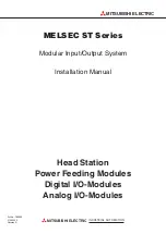
background image

MELSEC ST Series

Modular Input/Output System

Installation Manual

Head Station

Power Feeding Modules

Digital I/O-Modules

Analog I/O-Modules

Art.no.: 163534
21042005
Version A

INDUSTRIAL AUTOMATION

MITSUBISHI ELECTRIC

MITSUBISHI ELECTRIC

Summary of Contents for MELSEC ST Series

Page 1: ... Modular Input Output System Installation Manual Head Station Power Feeding Modules Digital I O Modules Analog I O Modules Art no 163534 21042005 Version A INDUSTRIAL AUTOMATION MITSUBISHI ELECTRIC MITSUBISHI ELECTRIC ...

Page 2: ... your relevant sales office or department refer to back of cover Current information and answers to frequently asked questions are also available through the Internet www mitsubishi automation com MITSUBISHI ELECTRIC EUROPE B V reserves the right to change the specifications of its products and or the contents of this manual at any time without prior notice MITSUBISHI ELECTRIC EUROPE B V 04 2005 2...

Page 3: ... Digital Input Modules 14 2 2 4 Transistor Output Modules Source Type 15 2 2 5 Contact Output Module 16 2 2 6 Analog Input Modules 17 2 2 7 Analog Output Modules 18 3 Description of the Modules 3 1 Head Station 19 3 1 1 Overview 19 3 1 2 LEDs of the Head Station 20 3 1 3 Switches 21 3 2 Base Modules 22 3 3 Power Distribution Modules 23 3 3 1 Overview 23 3 3 2 LEDs of the Power Distribution Modules...

Page 4: ... the Electronics Modules 35 4 4 Wiring 36 4 4 1 Connecting the Supply Voltage 36 4 4 2 Connecting the I O Signals 37 4 5 Connection of the PROFIBUS DP Cable 39 4 6 Start Up 40 5 Trouble Shooting 5 1 Checking the System Set Up 41 5 2 Head Station Self Diagnostics 41 5 3 Error Diagnostics using the LEDs 42 A Appendix A 1 External Dimensions of the Modules 43 A 1 1 Head station ST1H PB 43 A 1 2 Base ...

Page 5: ...operty Only accessories and peripherals specifically approved by MITSUBISHI ELECTRIC may be used Any other use or application of the products is deemed to be improper Relevant safety regulations All safety and accident prevention regulations relevant to your specific application must be observed in the system design installation setup maintenance servicing and testing of these products The regulat...

Page 6: ... permanent connection to the mains power supply must be inte grated in the building installations with an all pole disconnection switch and a suitable fuse 쎲 Check power cables and lines connected to the equipment regularly for breaks and insulation damage If cable damage is found immediately disconnect the equipment and the cables from the power supply and replace the defective ca bling 쎲 Before ...

Page 7: ...on modules of the ST series only The other system modules are supplied with power via internal connec tions Wiring requirements are significantly reduced because the supply voltage does not need to be connected to each individual module PROFIBUS connection Only the head station is connected to the PROFIBUS DP network Connection of the I O modules Peripherals are connected either via spring clamp t...

Page 8: ...n always consists of a head station which establishes the connection to the PROFIEBUS DP network At least one power distribution module and the digital and or analog I O modules are connected to the head station The I O modules consist of an electronics module and a base module which establishes the connection to the head station via screw clamp terminals or spring clamp terminals The elec tronics...

Page 9: ...modules Spring clamp terminals Screw clamp terminals Head station ST1H PB For connection to the PROFIBUS Not necessary Not necessary Power distribution modules Bus refreshing module ST1PSD For powering the head station Supply of 5 V DC and distribution of 24 V DC ST1B S4P2 H SET ST1B E4P2 H SET For increasing the capac ity of the 5 V DC supply ST1B S4P2 R SET ST1B E4P2 R SET Power feeding module S...

Page 10: ...module Digital modules excluding contact output modules Contact output modules DIN rail Power feeding module Power supply for voltage SYS Power supplies for voltage AUX ST1H PB ST1PSD ST1AD2 V ST1DA2 V ST1PDD ST1PDD ST1Y2 DE1 ST1X2 DE1 ST1Y2 R2 ST1Y2 R2 161 131 151 ST1X16 DE1 RUN ERR 21 11 41 31 61 51 81 71 101 91 121 141 111 11 31 51 71 91 111 131 151 21 41 61 81 101 121 141 161 12 32 52 72 92 11...

Page 11: ... condensation MELSEC ST Series 11 Specifications Item Specifications Operating ambient temperature 0 to 55 C Storage ambient temperature 25 to 75 C Ambient humidity for opera tion and storage 5 to 95 relative humidity non condensing Vibration resistance Conforms to JISB3501 and IEC61131 2 Intermittent Vibration Frequency Acceleration Amplitude half Sweep count for X Y Z 10 to 57 Hz 0 075 mm 10 tim...

Page 12: ...ical standards and characteristics EIA RS485 compliant Applicable cable Shielded twisted pair cable Network configura tion Bus type tree type when repeaters are used Data link method Polling Transmission encod ing method NRZ Transmission speed and maximum trans mission distance Transmission speed Transmission distance m per segment Max transmission dis tance when 3 repeaters are used m 9 6 kbps 12...

Page 13: ...imulator Peak to peak noise voltage 500 V noise width noise frequency 1 µs 25 to 60 Hz First transient noise compliant to IEC61000 4 4 2 kV Indication of operating status LED SYS Indicates that 5 V DC are output LED AUX Indicates that 24 V DC are output Number of occupied slices Width 2 slots 25 2 mm 1 slot 12 6 mm Number of occupied I O points 2 inputs and 2 outputs Internal power consumption 5 V...

Page 14: ... ON 씮 OFF Maximum current at 24 V DC 2 A During online module change the maximum inrush current is 2A per input for approx 5 ms Inputs per group 2 4 16 Dielectric withstand voltage 500 V AC for 1 minute across DC external terminals and FG Insulation resistance 10 MΩ across DC external terminals and FG checked with insulation resistance tester Noise durability Tested with noise simulator Peak to pe...

Page 15: ...suppressor Zener diode Protection One 4 0 A fuse unchangeable 햲 One 6 7 A fuse unchangeable 햲 Thermal protection and short circuit protection After cooling down resp elimination of the short circuit the operation will continue automatically Indication of activated protective function When a fuse blows the ERR LED is switched on and a signal is output to the head station 햳 When a protective functio...

Page 16: ... 35 100000 times at 24 V DC 1 A 100 V DC 0 1 A L R 7 ms Maximum switching frequency 3600 times hour Surge suppressor Not provided Fuse Not provided Dielectric withstand voltage 2830 V AC rms for 3 cycles operation altitude 2000 m Insulation resistance 10 MΩ across external terminals and FG checked with insulation resistance tester Noise durability Tested with noise simulator Peak to peak noise vol...

Page 17: ... C Digital output 16 bit Isolation method The input channels are isolated against the backplane bus by photocouplers There is no isolation between the channels Dielectric withstand voltage 500 V AC for 1 minute across the external DC terminals and FG Insulation resistance 10 MΩ across external DC terminals and FG checked with insulation resistance tester Noise durability Tested with noise simulato...

Page 18: ...output channels are isolated against the backplane bus by photocouplers There is no isolation between the channels Dielectric withstand voltage 500 V AC for 1 minute across the external DC terminals and FG Insulation resistance 10 MΩ across external DC terminals and FG checked with insulation resistance tester Noise durability Tested with noise simulator Peak to peak noise voltage 500 V noise widt...

Page 19: ...ostics and configuration a personal computer with the software GX Configurator DP installed version 6 0 or later is con nected with this Mini DIN socket 쐏 Buttons and RELEASE Used to make online module change and to reset the head station 쐄 PROFIBUS DP interface Connects the PROFIBUS DP cable to the head module 쐂 Display plate Write the station number of the head station on this plate 쐆 Base modul...

Page 20: ...he settings of the selected slice module were saved and the module can now be remounted Flickering After changing a slice module the settings are loaded to the new module OFF Online module change has been completed or is not selected DIA ON Extended diagnostic information being sent to master station Flickering Self diagnostics of head module being executed OFF No extended diagnostic information B...

Page 21: ...elf diagnostics If other values are set then an error will occur after switching on or resetting the head module The sum resulting from the switch settings for the single digits 8 4 2 and 1 may not exceed the value of 9 Description of the Modules MELSEC ST Series 21 Station number Settings 10s place 1s place 80 40 20 10 8 4 2 1 0 OFF OFF OFF OFF OFF OFF OFF OFF 1 OFF OFF OFF OFF OFF OFF OFF EIN 2 ...

Page 22: ...for extension 쐋 DIN rail mounting groove Mounts the head station to the DIN rail 쐏 FG contact Grounding metal spring on the back of the head station FG of all mounted modules ist connected via the conductive DIN rail 쐄 Fixing hook Hook for coupling with an adjacent base module 쐂 Coding element mounting holes The coding element is fixed in this hole automatically while mounting a slice module for t...

Page 23: ...ow the operating status of the module refer to chapter 3 3 2 Slice module fixing hooks both ends Hooks for mounting removing the slice module to from the base module Hold down the hooks at both ends and remove the module Coding elements Provided to prevent a wrong slice module from being inserted into the base module The slice module can be inserted only when the coding element of the base module ...

Page 24: ... rail 11 12 13 14 31 32 33 34 21 22 23 24 41 42 43 44 ST1B 4P2 SET LED LED status Meaning RUN ON Normally operating Flickering Flickering in 0 25 s intervals Selected as a module to be replaced online Power distribution modules cannot be changed while the station is operating Continue the selection until the RUN LED on the desired mod ule is flickering Flickering in 1 s intervals 쎲 Communication w...

Page 25: ... 22 24 24 V 24 G 5 V SG Base module External power supply for AUX ST1PDD Connection to the adjacent base module Connection to DIN rail 11 12 13 14 21 22 23 24 External Connections Terminal Block Terminal Signal 11 Not connected 12 24 V AUX 13 14 Shield 21 Not connected 22 24 V AUX 23 24 Shield ...

Page 26: ...es 쎲 Blue Analog output modules 쐇 I O status LEDs Indicate whether the inputs outputs are ON or OFF The LED is lit when the corresponding input output is ON 쐋 Face plate Use the symbol label to note the names of external connections A diagram of the wiring to the base module is printed on the surface When checking the wring diagram remove the symbol label Slice module fixing hooks both ends Hooks ...

Page 27: ...ing Flickering Flickering in 0 25 s intervals Selected as a module to be replaced online Flickering in 1 s intervals 쎲 Communication with the master station has stopped 쎲 Slave parameter setting error 쎲 Other slice module fault 쎲 Internal bus error OFF 쎲 The external power is off 쎲 Hardware fault 쎲 Internal bus error ERR ON Hardware fault For output modules ST1Y2 TE2 and ST1Y16 TE2 only The fuse h...

Page 28: ... 82 102 122 242 262 23 43 63 83 103 123 143 163 24 44 64 84 104 124 144 164 XF 24 V DC 24 V DC Inputs Base module ST1B 첸4X16 Shield X1 X2 X3 X4 X5 X6 XE X7 X8 X9 XA XB XC XD X0 Base module ST1B 첸3Y2 Output Y0 24 V DC Shield Output Y1 24 V DC Shield 11 12 13 21 22 23 11 31 51 71 91 111 131 151 12 32 52 72 92 112 132 152 13 33 53 73 93 113 133 153 21 41 61 81 101 121 141 161 22 42 62 82 102 122 242 ...

Page 29: ...ST1B 첸4IR2 COM DC AC DC AC COM 11 12 13 14 21 22 23 24 11 12 13 14 21 22 23 24 Voltage or current input CH2 Shield COM Voltage or current input CH1 Base module ST1B 첸4IR2 Shield COM Not connected Not connected 11 12 13 14 21 22 23 24 Voltage or current output CH2 Shield COM Voltage or current output CH1 Base module ST1B 첸4IR2 Shield COM Not connected Not connected ...

Page 30: ...fire can result The ST modules are designed for mounting on a DIN rail If the modules are not oper ated on a DIN rail then malfunctions can occur 4 2 Mounting the DIN Rail 쎲 Use a rail in accordance with DIN 50022 with a width of 35 mm to mount the modules In addition to anchoring the modules the DIN rail is also used to connect the device grounding of the individual modules For this reason the DI...

Page 31: ... 111 11 31 51 71 91 111 131 151 21 41 61 81 101 121 141 161 12 32 52 72 92 112 132 152 22 42 62 82 102 122 142 162 13 33 53 73 93 113 133 153 23 43 63 83 103 123 143 163 14 34 54 74 94 114 134 154 24 44 64 84 104 124 144 164 ST1X2 DE1 RUN ERR 21 11 11 21 12 22 13 23 14 24 ST1PSD RUN ERR PW 11 11 21 21 12 12 22 22 13 14 13 14 23 24 23 24 MITSUBISHI STATION ST1H PB ON RS 232C RELEASE RESET PROFIBUS ...

Page 32: ...ips see page 34 DIN rail 햲 햳 Head station Groove for DIN rail at the rear of the head station 햲 Lightly tilt the base module forwards lightly and hook it under the DIN rail with the lower limit of rail 햳 Now press the base module in the direc tion of the DIN rail until the module clicks into place and is securely anchored on the DIN rail 햴 Push the base module on the DIN rail to the left to establ...

Page 33: ...s are simplified with the colored wiring markers Color coding is listed in the following table Plug each wiring marker in the slots under neath the terminals Wiring marker Base module Colour of wiring marker Meaning Black Signal wires Red Positive pole of a DC voltage 24 V DC 5 V DC Blue Positive pole of a DC voltage 24 V DC 5 V DC N conductor of an AC voltage Red Blue System power supply Yellow G...

Page 34: ...ighten the end bracket s screw End bracket DIN rail 햲 햳 햴 햲 Guide an end bracket into the cutout of the end plate 햳 Place the end plate next to the last base module on the DIN rail 햴 Push the end plate with the end bracket to the left until it reaches the base module 햵 Firmly tighten the screw of the end bra cket through the hole in the end plate End plate Recess End bracket 햲 햳 햴 햵 DIN rail End p...

Page 35: ...e while the coding ele ment is anchored in the base module Nevertheless push the electronics modules all the way into the base module until it clicks into place Do not use excessive force if an electronics module cannot be inserted in a base module In this case check whether a code element is already installed in the base module Prior to mounting the electronics modules the head station the base m...

Page 36: ...ovides 24 V DC for the SYS and AUX voltages of the ST modules The wires with the supply voltage 24 V DC should be twisted together and laid out in the short est possible path Use the maximum possible cross section for these wires 2 5 mm2 The lines for direct current voltage supply 24 V DC may not be laid out together with lines that conduct high voltages high currents or I O signals To the extent ...

Page 37: ...inals and ST1A SLD E for screw clamp terminals are available for this purpose Metal conduit or cable channels that the wiring runs through must be earthed Lines that conduct input or output signals 24 V DC must be laid out separately from lines that conduct alternating current 110 230 V NOTE For line lengths over 200 m capacity losses may occur which can corrupt the input signals The following ill...

Page 38: ...TRIC Shield COM CH1 Shield COM CH1 Shield COM CH2 U or I Shield COM CH2 Single end connection Differential connection U or I U or I DC AC DC AC Y0 DC AC DC AC Y1 COM COM Load Load ST1Y2 R2 Relay of the module Relay of the module Shield COM CH1 Shield COM CH2 Voltage or current output Voltage output ...

Page 39: ...ON PLUS PG plugs the resistances are already installed and can be switched on For a plug without integrated resis tors three resistors must be connected according to the following circuit diagram The resistors are not included in the module s scope of delivery Installation MELSEC ST Series 39 Pin Layout of the socket PIN Symbol Name Meaning 1 SHIELD Shield protective earth 2 M24V Not used 3 B B쎾 R...

Page 40: ... module switches see page 21 햶 Connect the head station to the PROFIBUS see page 39 햷 Set the parameters of the head station as slave on the PROFIBUS using the GX Configurator DP software 햸 Use the GX Configurator DP software to set the parameters of the individual ST modules 햹 Set the parameters of the master station of the PROFIBUS DP network 햺 Start the data transfer with the ST station via the...

Page 41: ...cs module see page 9 Check whether the correct combination is used 쎲 Is the system shorter than 85 cm The total width of the ST Module connected to a head module may not exceed 85 cm see page 9 쎲 Is the power consumption of the modules within the capacity of the power supply It may be that the connected ST modules exceed the capacity of the internal 5 V supply The capacity of the 24 V supply can b...

Page 42: ...odule is not illuminated then check whether the LEDs RUN SYS and AUX of the power distribution modules are illuminated 쎲 If only the RUN LED of an ST module flashes slowly then replace the electronics module or base module 쎲 If the RUN LEDs of multiple ST modules arranged directly next to each other flash slowly then replace the base module that is installed to the left of the malfunctioning mod u...

Page 43: ...ad station ST1H PB Appendix MELSEC ST Series 43 14 5 67 5 50 5 74 5 114 5 69 26 5 31 2 5 MITSUBISHI STATION ST1H PB ON RS 232C RELEASE RESET PROFIBUS I F RUN M 1 ERR M 2 REL DIA SYN BF FRE 80 S T A T I O N N O 40 20 10 8 4 2 1 7 Alle dimensions are given in mm ...

Page 44: ...rminals ST1B E3Y2 117 6 45 2 48 3 ST1B E4X2 128 8 56 4 ST1B E4IR2 ST1B E4P2 H ST1B E4P2 R ST1B E4P2 D ST1B E6X4 154 4 82 0 Spring clamp terminals ST1B S3Y2 117 6 45 2 41 6 ST1B S4X2 128 8 56 4 ST1B S4IR2 ST1B S4P2 H ST1B S4P2 R ST1B S4P2 D ST1B S6X4 154 4 82 0 Unit mm 72 4 49 9 73 1 C 67 8 12 6 A B ...

Page 45: ...ries 45 Base Modules Dimensions mm A B C Screw clamp terminals ST1B E3Y16 117 6 45 2 48 3 ST1B E4X16 128 8 56 4 Spring clamp terminals ST1B S3Y16 117 6 45 2 41 6 ST1B S4X16 128 8 56 4 Unit mm 73 1 49 9 67 8 C 100 8 A 72 4 B ...

Page 46: ...A 1 3 Power Distribution Modules ST1PSD ST1PDD Appendix 46 MITSUBISHI ELECTRIC ST1PDD RUN ERR AUX 47 3 55 4 72 3 2 2 4 12 6 Unit mm Unit mm 47 3 55 4 ST1PSD RUN ERR SYS AUX 72 3 2 2 4 25 2 ...

Page 47: ... slot 12 6 mm Modules with a wide of eight slots 100 8 mm Appendix MELSEC ST Series 47 47 3 55 4 72 100 8 161 131 151 ST1Y16 TE2 RUN ERR 21 11 41 31 61 51 81 71 101 91 121 141 111 Unit mm Unit mm 47 3 55 4 72 3 2 2 4 12 6 ST1X2 DE1 RUN ERR 21 11 ...

Page 48: ...ice meltrade hu SIAPOWEL LATVIA Lienes iela 28 LV 1009 Riga Phone 371 784 22 80 Fax 371 784 22 81 e mail utu utu lv EUROPEAN REPRESENTATIVES UAB UTU POWEL LITHUANIA Savanoriu pr 187 LT 2053 Vilnius Phone 370 0 52323 101 Fax 370 0 52322 980 e mail powel utu lt INTEHSIS SRL MOLDOVA Cuza Voda 36 1 81 MD 2061 Chisinau Phone 373 0 2 562 263 Fax 373 0 2 562 263 e mail intehsis mdl net Koning Hartman B V...

Reviews: