


Part 5: Review on Replacement of MR-J2S-30 kW or Higher Capacity Models with MR-J4-DU_
5 - 13
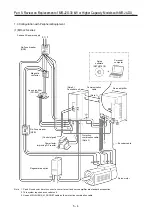
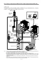
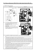
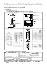
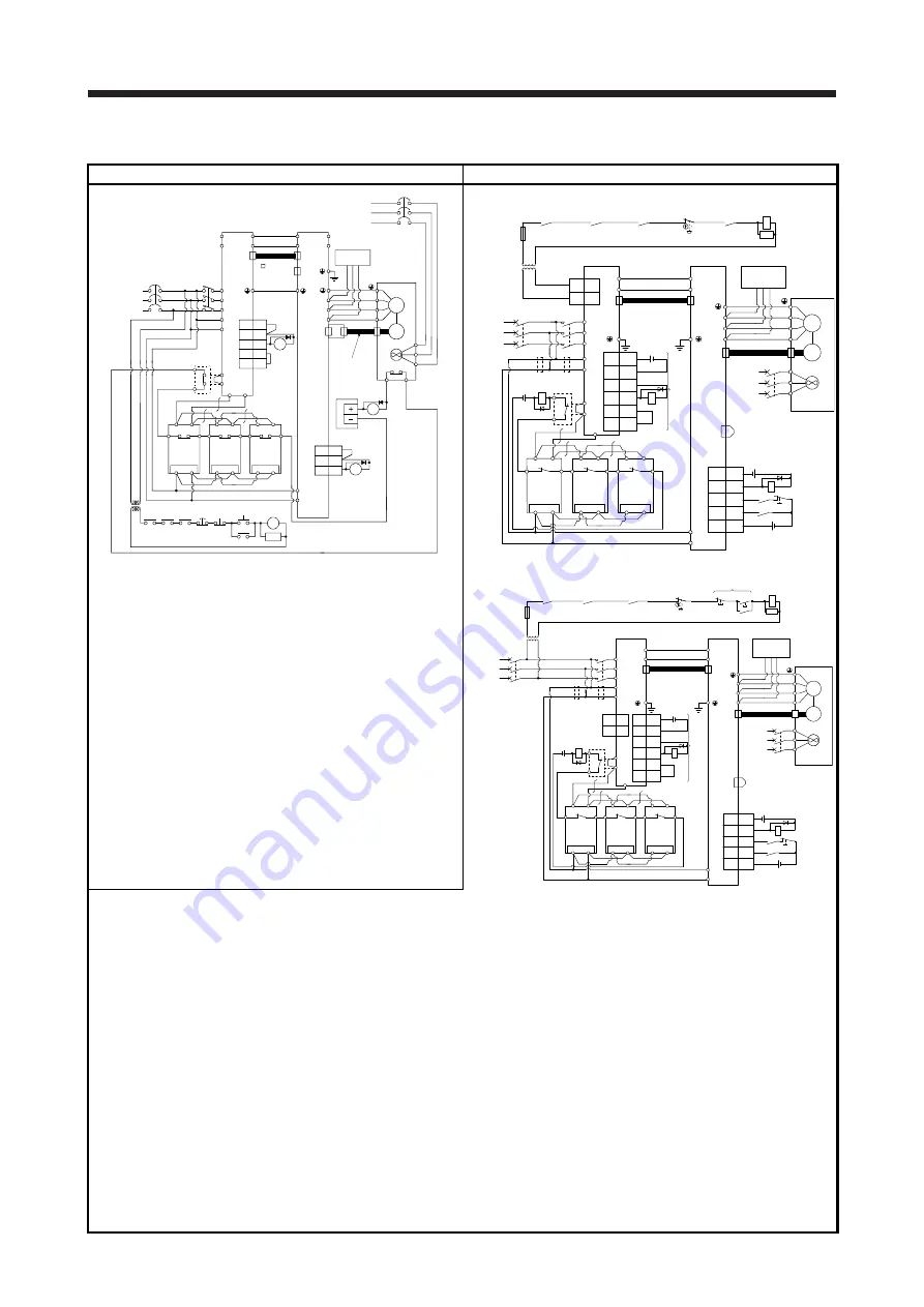
(3) General-purpose interface 400 V class
MR-J2S-_KA4 MR-J4-DU_A4
Converter unit
3-phase
380 to
480 V AC
50/60 Hz
Servo amplifier
MR-A-TM
connector
termination
(Option)
MR-J2HBUS
M cable
Servo motor
brake
Dynamic
Fan
24 V DC
power
Encoder
supply
Servo motor
Servo
thermal relay
relay
Motor thermal
Operation-ready
down
Step-
trans-
Fan
former
(Note1)
Regenerative
Fan
brake option
Fan
(Note1)
Regenerative
brake option
(Note1)
Regenerative
brake option
(Note2)
Converter
Encoder cable
CN1
Power factor improving
DC reactor (Option)
MC
L
1
L
2
L
3
L
11
L
21
NFB
13 COM
12
8
VDD
3
ALM
SE
5
SG
RA3
P
N
P
N
N
P
N
CN5
CN5A
CN2
RA2
BW
OSH1
BV
BU
M
C
P
P
1
P
2
ON
MC
MC
SK
RA1
RA3
RA2 EMG OFF
VDD
COM
ALM
RA1
OHS2
P
V
U
W
CN5B
CNB1
L
11
L
21
V
U
W
R400S400
G4
G3
C
P
G4
R400S400
G3
P
C
G4
R400 S400
G3
P
C
NFB
MR-HCN2
3
13
18
3-phase
380 to 460 V AC
50/60 Hz
When magnetic contactor drive output is enabled (factory setting)
MC
MCCB
RA2
L+
L-
L1
L2
L3
L11
L21
CN40
CN40A
M
V
U
W
V
U
W
TE2-2
L+
L-
TE2-1 (Note 15)
C
P1
P2
L11
L21
G4
G3
P
C
G4
G3
P
C
S400
R400
G4
G3
P
C
S400
R400
S400
R400
CN1
1
DICOM
5
DOCOM
6
DICOM
2
ALM
7
EM1
9
DOCOM
CN1
15
21
46
48
42
BW
BV
BU
MCCB
RA3
RA1
RA2
MC
SK
1
MC1
2
MC2
CNP1
(Note 3)
Step-down
transformer
RA3
CN8
Optional
thermal
Operation ready
OFF/ON
Drive unit
malfunction
Emergency stop
switch
(Note 6)
(Note 1)
Regenerative
option
MR-J3CDL05M
cable
Drive unit
3-phase
380 V AC to
480 V AC
(Note 13)
CN2
External
dynamic brake
(
optional
)
Encoder
Servo motor
(Note 5)
Power
supply
Power factor improving
DC reactor (
optional
)
(Note 2)
Cooling fan
(Note 1)
Regenerative
option
Cooling fan
(Note 1)
Regenerative
option
Cooling fan
(Note 9) Encoder cable
24 V DC
Cooling fan
(Note 8, 16)
24 V DC
(Note 12)
Short-circuit connector
(packed with the drive unit)
(Note 13)
(Note 10)
(Note 14)
(Note 11, 17)
(Note 11, 17)
Resistance regeneration
converter unit
Converter unit
malfunction
EM2
ALM
DICOM
DOCOM
SON
24 V DC
(Note 7)
Main circuit power supply
RA1
24 V DC
Note 1. This is a configuration for MR-RB138-4. Use three MR-RB138-4s
in a set, which provides permissible regenerative power of 3900
W.
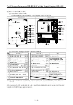
When magnetic contactor drive output is disabled
BW
BV
BU
(Note 5)
Power
supply
MCCB
Cooling fan
MC
(Note 6)
RA2
L+
L-
MR-J3CDL05M
cable
Drive unit
L1
L2
L3
L11
L21
MCCB
CN40A
(Note 13)
CN2
External
dynamic brake
(
optional
)
M
Encoder
V
U
W
V
U
W
Servo motor
TE2-2
L+
L-
TE2-1 (Note 15)
C
P1
P2
Power factor improving
DC reactor (
optional
)
(Note 2)
L11
L21
G4
G3
P
C
G4
G3
P
C
S400
R400
G4
G3
P
C
S400
R400
S400
R400
CN1
1
DICOM
5
DOCOM
6
DICOM
2
ALM
7
EM1
9
DOCOM
CN1
15
21
46
48
42
(Note 9) Encoder cable
24 V DC
(Note 8, 16)
CN40
1
MC1
2
MC2
CNP1
RA3
RA1
RA2
MC
MC
SK
RA3
24 V DC
(Note 11, 17)
(Note 13)
(Note 12)
Short-circuit connector
(packed with the drive unit)
CN8
(Note 10)
(Note 4)
(Note 14)
(Note 11, 17)
(Note 3)
Step-down
transformer
Optional
thermal
Drive unit
malfunction
Emergency stop
switch
(Note 1)
Regenerative
option
3-phase
380 V AC to
480 V AC
Cooling fan
(Note 1)
Regenerative
option
Cooling fan
(Note 1)
Regenerative
option
Cooling fan
Operation ready
ON
OFF
Converter unit
Converter unit
malfunction
EM2
ALM
DICOM
DOCOM
SON
24 V DC
(Note 7)
Main circuit power supply
RA1
24 V DC
2. When using a power factor improving DC reactor, remove the
short-circuit bar between P1 and P2.
3. Use a step-down transformer when the coil voltage of the
magnetic contactor is 200 V class.
4. Use an MR-J2HBUS_M_ SSCNET cable as a protection
coordination cable.
5. Use an external dynamic brake to this servo amplifier. Without an
external dynamic brake, the servo motor keeps running at an
emergency stop in a free run state, leading to an accident. Take
as many safety measures as possible in the system.
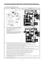
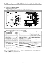
Note 1. This is for MR-RB13V-4. For the MR-RB13V-4, three units are used as one set (permissible regenerative power: 3900 W).
2. P1 and P2 are connected by default. When using the power factor improving DC reactor, connect P1 and P2 after removing the short bar across
them. Refer to section 8.6 for details.
3. A step-down transformer is required when the coil voltage of the magnetic contactor is 200 V class.
4. Connect the magnetic contactor wiring connector to CNP1 of the converter unit. If the connector is not connected, an electric shock may occur.
5. For specifications of the cooling fan power supply, refer to "Servo Motor Instruction Manual (Vol. 3)".
6. Use a magnetic contactor with an operation delay time (interval between current being applied to the coil until closure of contacts) of 80 ms or
less. The bus voltage decreases depending on the main circuit voltage and operation pattern, which may cause the forced stop deceleration to
shift to the dynamic brake deceleration. When dynamic brake deceleration is not required, slow the time to turn off the magnetic contactor.
7. To prevent an unexpected restart of the drive unit, configure a circuit to turn off EM2 in the drive unit when the main circuit power is turned off.
8. Use an external dynamic brake for the drive unit. Failure to do so will cause an accident because the servo motor does not stop immediately but
coasts at an alarm occurrence for which the servo motor does not decelerate to stop. Ensure the safety in the entire equipment. For alarms for
which the servo motor does not decelerate to stop, refer to chapter 6. For wiring of the external dynamic brake, refer to "MR-CV_/MR-
CR55K_/MR-J4-DU_(-RJ) Instruction Manual".
9. For the encoder cable, use of the option cable is recommended. For selecting cables, refer to "Servo Motor Instruction Manual (Vol. 3)".
10. This diagram shows sink I/O interface. For source I/O interface, refer to section "MR-CV_/MR-CR55K_/MR-J4-DU_(-RJ) Instruction Manual".
11. Install an overcurrent protection device (molded-case circuit breaker or fuse) to protect the branch circuit. (Refer to section 5.3.)
12. When not using the STO function, attach the short-circuit connector supplied with the drive unit.
13. Do not connect the servo motor of a wrong axis to U, V, W, or CN2 of the drive unit. Otherwise, a malfunction may occur.
14. For connecting servo motor power wires, refer to "Servo Motor Instruction Manual (Vol. 3)".
15. For the MR-J4-DU30K_4(-RJ) and MR-J4-DU37K_4(-RJ), the terminal block is TE2.
16. The external dynamic brake cannot be used for compliance with SEMI-F47 standard. Do not assign DB. Failure to do so will cause the drive unit
to become servo-off when an instantaneous power failure occurs.
17. The converter unit and the drive unit can be connected to the control circuit power supply (L11/L21) by daisy chain. Refer to section 5.2 for the
wire size and the selection of the overcurrent protection device.
Summary of Contents for MELSERVO-J2-Super Series
Page 18: ...Part 1 Summary of MR J2S MR J2M Replacement 1 1 Part 1 Summary of MR J2S MR J2M Replacement ...
Page 31: ...Part 1 Summary of MR J2S MR J2M Replacement 1 14 MEMO ...
Page 109: ...Part 3 Review on Replacement of MR J2S _B_ with MR J4 _B_ 3 32 MEMO ...
Page 161: ...Part 4 Review on Replacement of MR J2S _CP_ CL_ with MR J4 _A_ RJ 4 52 MEMO ...
Page 239: ...Part 6 Review on Replacement of MR J2M with MR J4 6 20 MEMO ...
Page 240: ...Part 7 Common Reference Material 7 1 Part 7 Common Reference Material ...
Page 284: ...Part 7 Common Reference Material 7 45 Click Update Project ...
Page 342: ...Part 8 Review on Replacement of Motor 8 1 Part 8 Review on Replacement of Motor ...
Page 409: ...Part 8 Review on Replacement of Motor 8 68 MEMO ...
Page 461: ...Part 9 Review on Replacement of Optional Peripheral Equipment 9 52 MEMO ...
Page 462: ...Part 10 Startup Procedure Manual 10 1 Part 10 Startup Procedure Manual ...


